
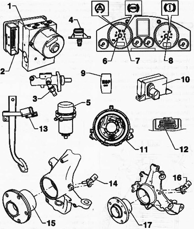
Pic. 6.62. Electrical/Electronic Components:
1 - ABS hydraulic block; 2 - ABS control unit; 3 - pressure sensor of the brake system; 4 - gain pressure sensor in the brake system; 5 - brake vacuum pump; 6 - control lamp ESP and ASR; 7 - control lamp ABS; 8 - control lamp of the brake system; 9 - key systems ASR and ESP; 10 - ESP sensor block; 11 - steering wheel angle sensor; 12 - diagnostic connector; 13 - brake light switch and brake pedal sensor; 14 - front right speed sensor / front left speed sensor; 15 - wheel bearing / wheel hub assembly; 16 - rear right speed sensor / rear left speed sensor; 17 - wheel bearing / wheel hub assembly.
Fault indication by control lamps
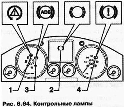
| Pos. | Designation (Pic. 6.64) |
| 1 | ESP and ASR warning lamp |
| 2 | Brake pad wear warning lamp |
| 3 | ABS warning lamp |
| 4 | Brake warning lamp |
If the ABS warning lamp 3 does not go out after the ignition is switched on and the control cycle is completed, the causes of the malfunction may be as follows:
- voltage less than 10 V;
- There is an ABS fault.
In the event of an ABS defect b, the anti-lock braking system remains disabled, while the braking system itself remains in working condition;
- There was a temporary RPM sensor failure since the last engine start.
In this case, the ABS warning lamp goes out automatically when the engine is restarted and then driven at a speed above 2.75 km/h;
- the connection from the instrument cluster to the ABS control unit is broken;
- the ABS warning lamp is defective.
ABS Warning Light and Brake Warning Light
If the ABS warning lamp goes out and the brake system warning lamp is on, then the causes of the malfunction may be as follows:
- the brake fluid level is too low.
Three warning tones are heard after the ignition is switched on.
- faulty wiring to the brake system warning lamp K118
If the ABS warning lamp 3 and the brake system warning lamp 4 are on, there is a malfunction in the ABS system. In the event of a malfunction of the ABS, a change in braking force must be taken into account.
WARNING: After the ABS warning lamp and the brake system warning lamp come on, the rear wheels may lock up prematurely when braking.
ESP and ASR warning lamp
If the ESP and ASR warning lamp does not go out after the ignition is turned on and the control cycle is completed, the causes of the malfunction may be as follows:
- there is a malfunction that affects only the ASR / ESP. The vehicle's ABS/EDS and EBV security systems remain fully operational. Interrogate the fault memory;
- short to positive in the ASR / ESP button;
- short to ground control lamp control ESP and ASR;
- Interrupted connection from the instrument cluster to terminal 31 of the ABS control unit;
- the ASR/ESP system has been deactivated with the ASR/ESP button.
If the ESP and ASR warning lamp flashes while driving, the ASR or ESP systems are in regulation mode.
Brake warning lamp
If the brake system warning lamp does not go out after switching on the ignition, this may be due to the following reasons:
- the parking brake is applied;
- the switch of a control lamp of brake system is faulty or incorrectly adjusted;
- there is a wiring error. Carry out an electrical check.
The parking brake contact switch informs the ABS control unit whether the parking brake is applied or not. When the parking brake is applied, ESP control is adversely affected.
Brake pad wear warning lamp
If the brake pad wear indicator lamp does not go out 3 seconds after the ignition is switched on or lights up while driving, the following faults may be the cause:
- brake pads may be worn.
Check the brake pads of the front and rear wheels. Replace pads if worn;
- there is a wiring fault.
Removal and installation of components of the ABS system on the front and rear axles
The ABS components on the front axle are shown in fig. 6.65.
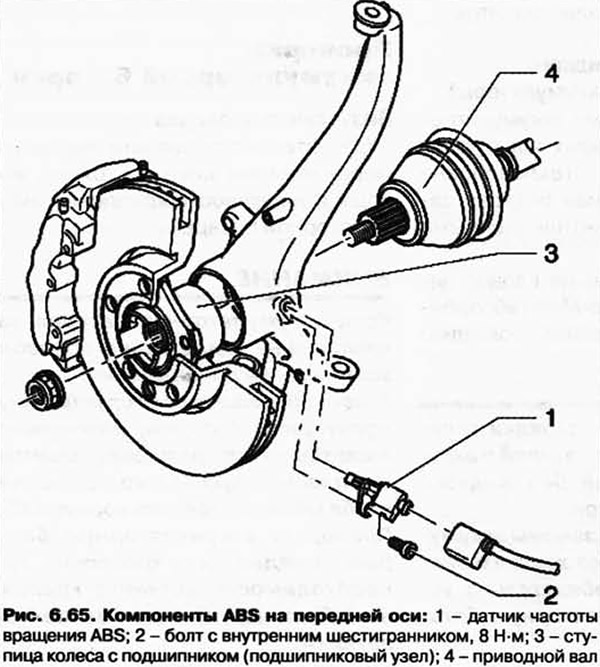
Removal and installation of the speed sensor on the front axle
Raise the vehicle.
Disconnect plug connection 1 of speed sensor cable and speed sensor (pic. 6.66).
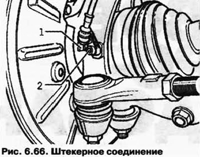
Remove bolt 2 from wheel bearing housing.
Remove the ABS speed sensor from the wheel bearing housing.
Installation
Before installing the RPM sensor, clean the hole and apply some grease around the entire diameter.
Insert the speed sensor into the hole in the wheel bearing housing and tighten the bolt to 8 Nm.
Connect the speed sensor to the sensor cable.
Removal and installation of components of the ABS system on the rear axle
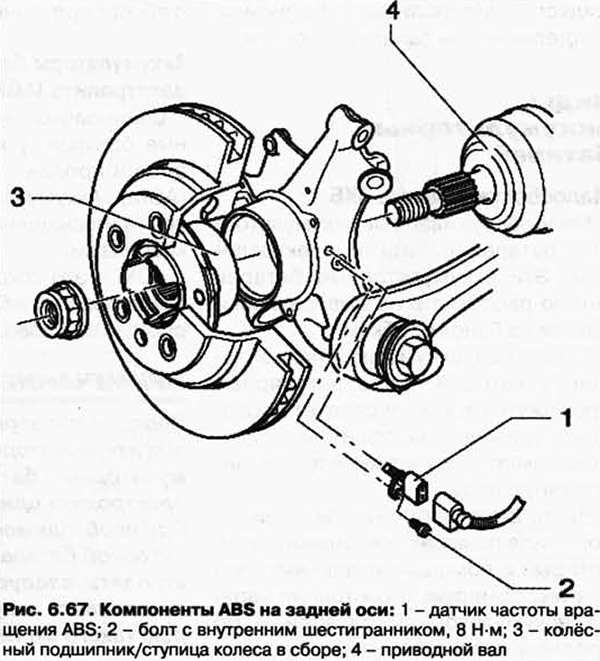
The ABS components on the rear axle are shown in fig. 6.67.
Removal and installation of the speed sensor on the rear axle
Raise the vehicle.
Disconnect plug connection 1 of speed sensor cable and speed sensor (pic. 6.68).
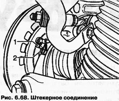
Remove bolt 2 from wheel bearing housing.
Remove the ABS speed sensor from the wheel bearing housing.
Before installing the RPM sensor, clean the hole and apply some grease around the entire diameter.
Insert the speed sensor into the hole in the wheel bearing housing and tighten the bolt to 8 Nm.
Connect the speed sensor to the sensor cable.
Visitor comments