
Car front suspension Volkswagen Touareg 1

Subframe, stabilizer bar, lower control arm
Pic. 4.46. Assembly assembly diagram - subframe, stabilizer, lower suspension arm: 1 - front main gear; 2 - subframe; 3 - self-locking nut; 4 - a bolt with a six-sided head; 5 - a...
Pic. 4.46. Assembly assembly diagram - subframe, stabilizer, lower suspension arm: 1 - front main gear; 2 - subframe; 3 - self-locking nut; 4 - a bolt with a six-sided head; 5 - a...

Removal and installation of a stretcher
Removing The subframe is removed using a scissor lift table. Install shorter, safety bolts at the front mounting points of the engine mount bracket. The subframe is removed...
Removing The subframe is removed using a scissor lift table. Install shorter, safety bolts at the front mounting points of the engine mount bracket. The subframe is removed...

Switchable stabilizer
Pic. 4.59. Switchable Stabilizer Components: 1 - front switchable stabilizer; 2 - stabilizer bearing; 3 - hydraulic pipeline; 4 - front suspension stabilizer disconnect sensor; 5...
Pic. 4.59. Switchable Stabilizer Components: 1 - front switchable stabilizer; 2 - stabilizer bearing; 3 - hydraulic pipeline; 4 - front suspension stabilizer disconnect sensor; 5...

Removing the switchable stabilizer
ATTENTION: Switchable stabilizers must be switched on before starting work. Otherwise, unintentional activation of the stabilizers may result in injury. Switch on the hydraulic...
ATTENTION: Switchable stabilizers must be switched on before starting work. Otherwise, unintentional activation of the stabilizers may result in injury. Switch on the hydraulic...

Checking the level and topping up the oil of the hydraulic system of the switchable stabilizers
Switch on the hydraulic system with the help in non-pressure mode. Remove the rear left lamp. Remove the plug from the filler hole (pic. 4.63). Cut off the tip of the atomizer...
Switch on the hydraulic system with the help in non-pressure mode. Remove the rear left lamp. Remove the plug from the filler hole (pic. 4.63). Cut off the tip of the atomizer...

Pumping a switchable stabilizer
Switch on the hydraulic system with the help in non-pressure mode. Check the oil level in the hydraulic pump. Connect the hose to the bleed nipple (pic. 4.66). Secure the hose to...
Switch on the hydraulic system with the help in non-pressure mode. Check the oil level in the hydraulic pump. Connect the hose to the bleed nipple (pic. 4.66). Secure the hose to...

Front wheel suspension
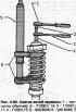
Pic. 4.67. Front suspension components: 1 - a bolt with a six-sided head; 2 - support bracket; 3 - self-locking nut; 4 - body level sensor; 5 - a bolt with a six-sided head; 6 -...
Pic. 4.67. Front suspension components: 1 - a bolt with a six-sided head; 2 - support bracket; 3 - self-locking nut; 4 - body level sensor; 5 - a bolt with a six-sided head; 6 -...

Removal and installation of an amortization rack
Removing Remove the wheel. Unscrew the connecting rod from the stabilizer. Unscrew the drive shaft from the main gear. To loosen bolts, use a socket with a nominal inside diameter...
Removing Remove the wheel. Unscrew the connecting rod from the stabilizer. Unscrew the drive shaft from the main gear. To loosen bolts, use a socket with a nominal inside diameter...

Removing and installing body level sender G78/G289 on vehicles with suspension struts
Removing To remove the body level sensor, it is necessary to dismantle the spring strut and support bracket. Remove the shock absorber. Removing the left support bracket Remove...
Removing To remove the body level sensor, it is necessary to dismantle the spring strut and support bracket. Remove the shock absorber. Removing the left support bracket Remove...

Wheel support
Pic. 4.75. Support components: 1 - wheel bearing housing; 2 - drive shaft; 3 - transverse lever; 4 - self-locking nut; 5 - wheel hub bearing; 6 - retaining ring; 7 - wheel hub; 8...
Pic. 4.75. Support components: 1 - wheel bearing housing; 2 - drive shaft; 3 - transverse lever; 4 - self-locking nut; 5 - wheel hub bearing; 6 - retaining ring; 7 - wheel hub; 8...
Removing the coil spring
Compress the spring to release the top spring cup. Unscrew the hex nut from the piston rod. Remove the individual suspension strut parts and the spring using the spring tie VAS...
Compress the spring to release the top spring cup. Unscrew the hex nut from the piston rod. Remove the individual suspension strut parts and the spring using the spring tie VAS...

Installing the coil spring
Insert the top support 2 into the top cup 1 (pic. 4.82). In this case, the protrusion arrow A must coincide with the recess - arrow B. Install the spring on the lower holder VAS...
Insert the top support 2 into the top cup 1 (pic. 4.82). In this case, the protrusion arrow A must coincide with the recess - arrow B. Install the spring on the lower holder VAS...
This section is available on russian, bulgarian, belarusian, ukrainian, serbian, croatian, romanian, polish, slovak, hungarian
Similar sections from other manuals for VW cars:
Chassis: Front suspension Volkswagen Passat B2 (1981-1988)
Chassis: Front suspension Volkswagen Golf 1 (1974-1984, petrol)
Chassis: Front suspension Volkswagen Polo 3 (1995-2003)
Chassis: Front suspension Volkswagen Tiguan 1 (2007-2015)
Chassis: Front suspension Volkswagen Transporter T3 (1979-1992)
Chassis: Front suspension Volkswagen Beetle (1960-1986)
Touareg 1
- General information
- Vehicle device
- Controls and instruments
- Seats and safety
- Maintenance and management
- Power unit
- Engine checks
- Petrol engine 3.2L
- Petrol engine 4.2L
- Diesel engine 5.0L
- Cooling system
- Lubrication system
- Injection system
- Exhaust system
- Fuel supply system
- Transmission
- Automatic gearbox 09D
- Mechanical gearbox 08D
- Cardan shaft
- Chassis
- Wheels and tires
- Front suspension
- Rear suspension
- Steering gear
- Brake system
- Body
- Outdoor elements
- Electrical equipment
- Battery
- Generator and starter
- Instruments and wipers
VWmanual.ru © 2016-2024 | Mobile version | News and articles | Sitemap: EN BG BY UA RS HR RO PL SK HU | Write message | Site search
Passat B2 • Passat B3 • Passat B4 • Passat B5 • Passat B6 • Golf 1, diesel • Golf 1, petrol • Golf 2, petrol • Golf 2 • Golf 3 • Golf 4 • Golf 5 • Polo 3 • Polo 4 • Touareg 1 • Tiguan 1 • Sharan 1 • Transporter T3 • Transporter T4 • Beetle • Caddy 3 •
Passat B2 • Passat B3 • Passat B4 • Passat B5 • Passat B6 • Golf 1, diesel • Golf 1, petrol • Golf 2, petrol • Golf 2 • Golf 3 • Golf 4 • Golf 5 • Polo 3 • Polo 4 • Touareg 1 • Tiguan 1 • Sharan 1 • Transporter T3 • Transporter T4 • Beetle • Caddy 3 •