



Removal
Remove the wheel.
Unscrew the connecting rod from the stabilizer.
Unscrew the drive shaft from the main gear. Use a 12mm nominal internal diameter socket or a 14mm nominal internal diameter socket to unscrew the bolts.
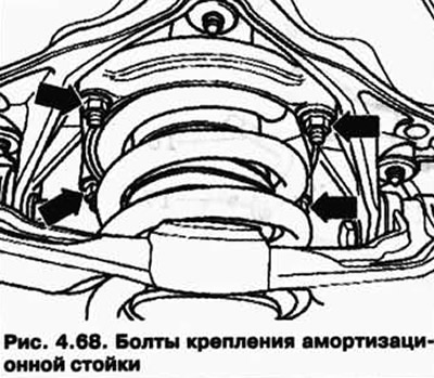
Unscrew the shock absorber strut from the body (Fig. 4.68).
Rotate the wheel hub so that one of the wheel bolt holes is at the top.
Attach the T10149 support using the wheel bolt.
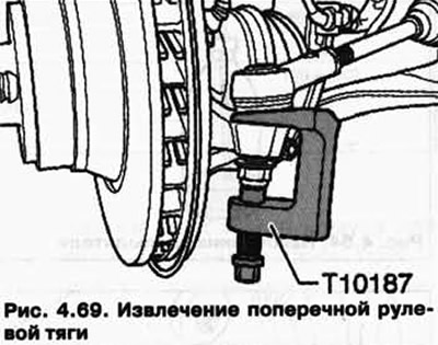
Press the tie rod out of the wheel hub bearing housing (Fig. 4.69).
Press out the upper lever (fig. 4.52).
Unscrew the bolt securing the shock absorber strut to the lower arm.
Do not lower the wheel bearing housing any further than necessary.
Remove the bolt from the lower arm and remove the shock absorber strut.
Installation
Installation is carried out in reverse order.
Tightening torques
| Component | Tightening torque, Nm |
| Shock absorber strut to the body (Use new nuts) | 30 |
| Shock absorber strut to lower arm (Use a new bolt and nut) | 150 + 90° |
| Upper arm to bearing housing (Use a new nut) | 95 |
| Wishbone to wheel bearing housing (Use a new nut) |
Visitor comments