
English Русский
Български
Беларускі
Український
Српски
Hrvatski
Română
Polski
Slovenský
Magyar
  |  Articles  |  Sitemap  |  Contacts  |    |
Car maintenance Ford Car maintenance Hyundai Car maintenance Chevrolet Car maintenance BMW Car maintenance Audi Car maintenance Opel Car maintenance AvtoVAZ
VWmanual.ru


Main   Passat   Golf   Polo   Touareg   Tiguan   Sharan   Transporter   Others  
LT 28 (1975-1991) LT 2D (1996-2003) Beetle (1960-1986) Caddy 3 (2003-2010)

Removal and installation the shock absorber strut (VW Caddy 3)

  • Main
  • Volkswagen
  • Caddy 3
  • Chassis
  • Car suspension
  • Removal and installation the shock absorber strut
            0


Contents: Removal ↓ Installation ↓

Removal


1. Loosen the hub bolt.

Caution: The vehicle must not stand on its wheels. Once the bolt is loosened, the wheel bearing may be damaged by the weight of the vehicle.


2. Remove the wheel.

3. Unscrew the stabilizer bar (arrow) from the shock absorber bar.
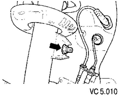
3. Unscrew the stabilizer bar (arrow) from the shock absorber bar.


4. Disconnect the wheel speed sensor wires from the shock absorber strut.

5. Unscrew the nuts (arrows).
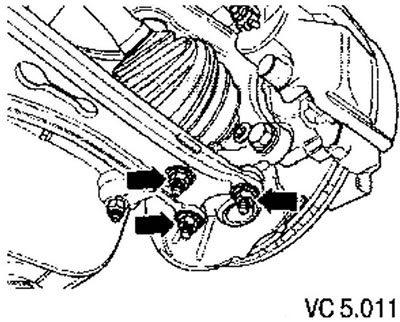
5. Unscrew the nuts (arrows).


6. Disconnect the triangular lever from the ball joint and, accordingly, from the steering knuckle.

7. Remove the drive shaft from the wheel hub.

8. Tie the drive shaft to the body.

Caution: The drive shaft must not hang downwards, as this will damage the inner joint.


9. Screw the ball joint to the wishbone.


10. Using a jack, push the steering knuckle upwards.
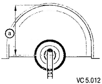
10. Using a jack, push the steering knuckle upwards.


11. Remove the strut mounting bolt in the steering knuckle (arrow).
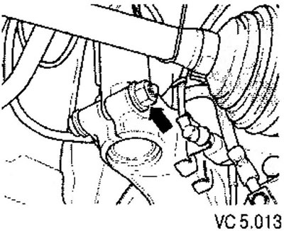
11. Remove the strut mounting bolt in the steering knuckle (arrow).


12. Insert the spacer (1) into the slot in the steering knuckle and, by turning it, widen the slot in the steering knuckle. In this case, you should press the brake disc with your hand in the direction of the shock absorber strut. Otherwise, the shock absorber strut may become misaligned in the steering knuckle hole.
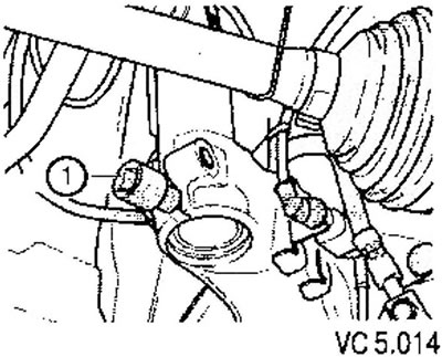
12. Insert the spacer (1) into the slot in the steering knuckle and, by turning it, widen the slot…


13. Lower the jack pressing the triangular lever and remove the steering knuckle from the shock absorber.


14. Tie the steering knuckle to the console with wire (subframe).

15. Remove the jack from under the steering knuckle.

Caution! The jack should not be left under the vehicle longer than necessary.


16. Remove the water drainage box on the front wall.

17. Loosen the hex bolts of the upper shock absorber support (arrows) and remove the shock absorber strut.
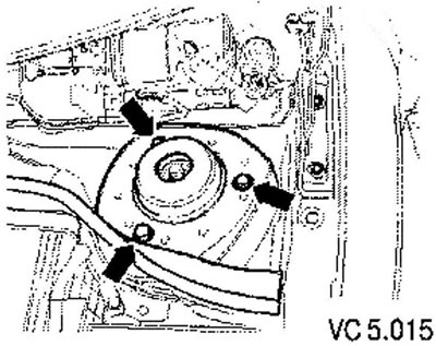
17. Loosen the hex bolts of the upper shock absorber support (arrows) and remove the shock absorber…


Installation


1. Install the shock absorber strut, making sure that both arrows (arrows) are directed parallel to the longitudinal axis of the vehicle.
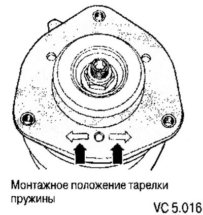
1. Install the shock absorber strut, making sure that both arrows (arrows) are directed parallel to…


2. Tighten the upper shock absorber support bolts (arrows).
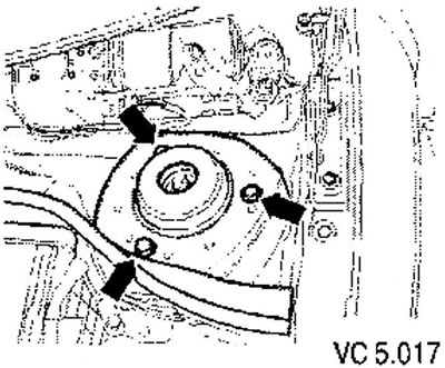
2. Tighten the upper shock absorber support bolts (arrows).


3. Using a jack, lift the steering knuckle upwards.

4. Insert the shock absorber strut into the hole in the steering knuckle,

5. Remove the support wire from the steering knuckle (see figure VC5.012).

6. Carefully raise the steering knuckle with a jack until the mounting bolt (arrow) can be installed.
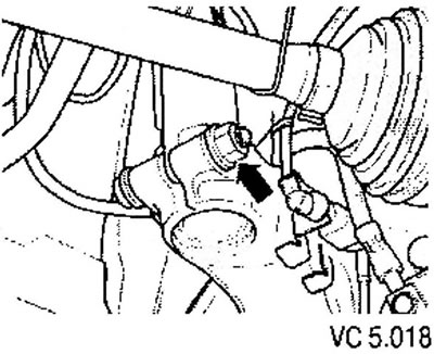
6. Carefully raise the steering knuckle with a jack until the mounting bolt (arrow) can be…


7. When lifting, press the brake disc towards the shock absorber strut. Otherwise, the shock absorber strut may become skewed in the 8th hole of the steering knuckle.

8. Remove the spacer.

9. Tighten the steering knuckle mounting bolt (arrow).

10. Remove the jack from under the car.

11. Unscrew the nuts (arrows).

12. Pull the steering knuckle outward and insert the drive shaft into the wheel hub. In this case, you need to ensure that the boot is not damaged.

13. Screw the ball joint installed on the steering knuckle to the wishbone.
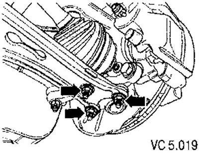
13. Screw the ball joint installed on the steering knuckle to the wishbone.


Further installation is carried out in reverse order.

This article is available at russian, bulgarian, belarusian, ukrainian, serbian, croatian, romanian, polish, slovak, hungarian
The text has been checked: Kolesnikov Artem

Share information:

Previous articles
Steering knuckle assembly with hub
Tightening torques for fasteners of front suspension components and assemblies
Removal and installation the ball joint
Checking the condition of ball joints
Setting the suspension to a position corresponding to the curb weight
Removal and installation the subframe
Next articles
Rear suspension repair
Tightening torques for threaded connections in the rear suspension


Similar articles from other manuals for VW cars:
Removal and installation the front shock absorber strut Passat B3 (1988-1993)
Installing the shock absorber strut on the supports Golf 1 (1974-1984, diesel)
Shock absorber strut Polo 3 (1995-2003)
Removal and installation the shock absorber strut Touareg 1 (2002-2006)
The structure of the shock absorber strut Tiguan 1 (2007-2015)
Coil spring and shock absorber Sharan 1 (1995-2000)
Throttle body Shock Absorber Transporter T4 (1990-2003)
Link to this page in different formats


Visitor comments


No comments yet


How much will 37 + 27 =


Caddy 3 
  • General information
  • User manual
  • Daily care
  • Maintenance
  • Petrol engines 1.4 l
  • Engine repair
  • Cooling and lubrication system
  • Power and exhaust system
  • Petrol engines 1.6 l
  • Engine repair
  • Cooling and lubrication system
  • Power and exhaust system
  • Diesel engines
  • Engine repair
  • Cooling and lubrication system
  • Power and exhaust system
  • Transmission
  • Mechanical gearbox 0AH
  • Mechanical gearbox 0A4
  • Drive shafts
  • Chassis
  • Car suspension
  • Steering
  • Brake system
  • Body and wiring diagrams
  • Interior and exterior
  • Electrical circuits
Beetle 
  • General information
  • Maintenance
  • Power unit
  • Engine repair
  • Cooling and lubrication system
  • Supply system
  • Exhaust system
  • Transmission
  • Clutch
  • Car gearbox
  • Chassis
  • Front suspension
  • Rear suspension
  • Steering
  • Brake system
  • Wheels and tires
  • Body
  • Exterior
  • Electrical equipment
  • Equipment and devices
  • Power devices
  • Electrical circuits
LT 2D 
  • General information
  • User manual
  • Maintenance
  • Power unit
  • Petrol engines 2.3 l
  • Diesel engines 2.5 l
  • Diesel engines 2.8 l
  • Injection system (diesel 2.8 l)
  • Transmission
  • Clutch
  • Manual gearbox
  • Differential
  • Chassis
  • Car suspension
  • Steering system
  • Brake system
  • Body
  • Body elements
  • Heating system
  • Electrical equipment
  • Equipment and devices
  • Electrical circuits
LT 28 
  • General information
  • Maintenance
  • Power unit
  • Petrol engines 2.0L
  • Petrol engines 2.4L
  • Diesel engines
  • Cooling and heating
  • Fuel and exhaust system
  • Ignition system
  • Transmission
  • Clutch
  • Car gearbox
  • Cardan shaft
  • Rear axle
  • Chassis
  • Brake system
  • Car suspension
  • Steering system
  • Body
  • Body elements
  • Doors, locks and windows
  • Electrical equipment
  • Power devices
  • Equipment and devices
  • Electrical circuits
VWmanual.ru © 2016-2026 | Mobile version | News and articles | Sitemap: EN BG BY UA RS HR RO PL SK HU | Write message | Site search
Passat B2 • Passat B3 • Passat B4 • Passat B5 • Passat B6 • Golf 1, diesel • Golf 1, petrol • Golf 2, petrol • Golf 2 • Golf 3 • Golf 4 • Golf 5 • Polo 3 • Polo 4 • Touareg 1 • Tiguan 1 • Sharan 1 • Transporter T3 • Transporter T4 • LT 28 • LT 2D • Beetle • Caddy 3 •
Our website uses cookies to ensure functionality and convenience.