
Manual gearbox 0AH car Volkswagen Caddy 3

Manual transmission identification data
1 - Letter designation and production date of the gearbox 2 - Manual transmission number 0AH Manual transmission number 0AN Letter designation and date of production of the...
1 - Letter designation and production date of the gearbox 2 - Manual transmission number 0AH Manual transmission number 0AN Letter designation and date of production of the...

Types and device manual transmission
Transmission diagram Arrows show the direction of movement I, II, III, IV, V, R. Gears A. Main gear 1. Engine 2. Clutch 3. Manual transmission 4. Primary shaft 5. Output shaft 6....
Transmission diagram Arrows show the direction of movement I, II, III, IV, V, R. Gears A. Main gear 1. Engine 2. Clutch 3. Manual transmission 4. Primary shaft 5. Output shaft 6....

Description of the clutch design
1. Release bearing 2. Screw: 5 Nm 3. Clutch release lever 4. Spring latch 5. Guide sleeve 6. Primary shaft seal 7. Ball stop: 20 Nm 8. Gearbox 9. Hex head screw: 20 Nm 10. Stopper...
1. Release bearing 2. Screw: 5 Nm 3. Clutch release lever 4. Spring latch 5. Guide sleeve 6. Primary shaft seal 7. Ball stop: 20 Nm 8. Gearbox 9. Hex head screw: 20 Nm 10. Stopper...

Repair of the clutch release mechanism
Remove the screws to remove the clutch release lever (indicated by arrows). Then remove the clutch release lever with release bearing and guide sleeve from the input shaft and...
Remove the screws to remove the clutch release lever (indicated by arrows). Then remove the clutch release lever with release bearing and guide sleeve from the input shaft and...

Gearshift Mechanism — Design Description
Attention! If the radio is coded, write down its code, When repairing the gear shift mechanism in the engine compartment (1) disconnect the ground wire from the battery (2) and...
Attention! If the radio is coded, write down its code, When repairing the gear shift mechanism in the engine compartment (1) disconnect the ground wire from the battery (2) and...

Gearbox — removal
Attention! With the ignition off, disconnect the ground from the battery. 1. Remove the casing from the engine. 2. Remove the air filter housing. 3. Remove the battery along with...
Attention! With the ignition off, disconnect the ground from the battery. 1. Remove the casing from the engine. 2. Remove the air filter housing. 3. Remove the battery along with...

Gearbox — installation
Please follow the instructions below before installation. All threaded holes into which self-locking screws have been inserted must be cleaned of residues of threadlocker. All...
Please follow the instructions below before installation. All threaded holes into which self-locking screws have been inserted must be cleaned of residues of threadlocker. All...

Checking the oil level in the manual transmission
To check the oil level, unscrew the oil level plug (arrow). The oil level must be at the bottom of the hole. Screw plug tightening torque: 25 Nm.
To check the oil level, unscrew the oil level plug (arrow). The oil level must be at the bottom of the hole. Screw plug tightening torque: 25 Nm.

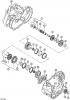
Parts and assemblies of manual transmission type 0AH
1. First gear 2. Second gear 3. Third gear 4. Fourth gear 5. Fifth gear 6. Gearbox housing cover 7. Crankcase 8. Intermediate reverse gear 9. Gearshift mechanism 10. Clutch...
1. First gear 2. Second gear 3. Third gear 4. Fourth gear 5. Fifth gear 6. Gearbox housing cover 7. Crankcase 8. Intermediate reverse gear 9. Gearshift mechanism 10. Clutch...

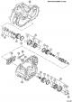
Removal and installation of a cover of a crankcase of a box and gear wheels of 5th transfer
1. Crankcase 2. 5th gear 3. Retaining ring (replaced by a new one) 4. Gasket 5. Gearbox housing cover 6. Screw 5 Nm + 90° (replaced by a new one) 7. Retaining ring (replaced by a...
1. Crankcase 2. 5th gear 3. Retaining ring (replaced by a new one) 4. Gasket 5. Gearbox housing cover 6. Screw 5 Nm + 90° (replaced by a new one) 7. Retaining ring (replaced by a...

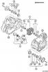
Removal and installation of the manual transmission housing
Carter KP: 1. Cone head screw: 25 Nm 2. Shaft with flange and spring 3. Screw: 5 Nm + 90° (replaced by a new one) 4. Clutch housing 5. Carter KP 6. Clutch release lever 7. Screw:...
Carter KP: 1. Cone head screw: 25 Nm 2. Shaft with flange and spring 3. Screw: 5 Nm + 90° (replaced by a new one) 4. Clutch housing 5. Carter KP 6. Clutch release lever 7. Screw:...

Removal and installation of input shaft, output shaft, differential
Removal and installation of the input shaft, output shaft, differential, gearshift mechanism and inclusion forks List of assemblies and parts of the input shaft, output shaft,...
Removal and installation of the input shaft, output shaft, differential, gearshift mechanism and inclusion forks List of assemblies and parts of the input shaft, output shaft,...

Gearbox disassembly
1. Drain gear oil. 2. Remove the clutch release lever (A). release bearing and guide bush (arrows). 3. Unscrew the fastening screw of the right flange shaft (IN). 4. Remove the...
1. Drain gear oil. 2. Remove the clutch release lever (A). release bearing and guide bush (arrows). 3. Unscrew the fastening screw of the right flange shaft (IN). 4. Remove the...

Gearbox Assembly
1. Fix primary (2) and secondary shaft (1) in bracket with deep groove ball bearing. 2. Install the mechanism (forks) inclusion (4) into the annular groove of the gear clutch. 3....
1. Fix primary (2) and secondary shaft (1) in bracket with deep groove ball bearing. 2. Install the mechanism (forks) inclusion (4) into the annular groove of the gear clutch. 3....

Internal shift mechanism manual transmission
Specification of parts of an assembly unit «Internal shift mechanism» Manual transmission type 0AH to drawing VC4.053 Pos. Part Number Name Note PC. 1 0AF 301 230 A Switch block 1...
Specification of parts of an assembly unit «Internal shift mechanism» Manual transmission type 0AH to drawing VC4.053 Pos. Part Number Name Note PC. 1 0AF 301 230 A Switch block 1...

Dismantling and assembly of the internal mechanism of inclusion of transfers
List of elements for drawing VC 4.054: 1. Block shift fork. 2. Switching element 3-4th gears. 3. Angular contact ball bearing. 4. Clamping bar (be sure to replace). 5. Switching...
List of elements for drawing VC 4.054: 1. Block shift fork. 2. Switching element 3-4th gears. 3. Angular contact ball bearing. 4. Clamping bar (be sure to replace). 5. Switching...
Dismantling and assembly of the input shaft
Specification of parts of an assembly unit «input shaft» Manual transmission type 0AH to drawing VC4.057 Pos. Detail number Name Note (1*) PC. 1 02T311 103K input shaft Z=ll+22...
Specification of parts of an assembly unit «input shaft» Manual transmission type 0AH to drawing VC4.057 Pos. Detail number Name Note (1*) PC. 1 02T311 103K input shaft Z=ll+22...

Disassembly and assembly of the hub with a sliding sleeve of the synchronizer of 3rd and 4th gears
Install the sliding sleeve on the hub. At the same time, the ends (A) hubs and recesses for crackers (IN) couplings must match. 3rd and 4th gear synchroniser hub arrangement (see...
Install the sliding sleeve on the hub. At the same time, the ends (A) hubs and recesses for crackers (IN) couplings must match. 3rd and 4th gear synchroniser hub arrangement (see...

Checking the synchronizer ring for wear
Press the blocking ring against the synchronizer sleeve and measure the distance (A) between them. When installing new parts for 3rd, 4th and 5th gears, the opening should be...
Press the blocking ring against the synchronizer sleeve and measure the distance (A) between them. When installing new parts for 3rd, 4th and 5th gears, the opening should be...

Determining the thickness of the thrust ring
Install 2.0mm Thrust Ring (A). Compress the input shaft. Measure the gap between the thrust ring (A) and inner ring (IN) tool (WITH). Determine the thickness of the ring using the...
Install 2.0mm Thrust Ring (A). Compress the input shaft. Measure the gap between the thrust ring (A) and inner ring (IN) tool (WITH). Determine the thickness of the ring using the...

Disassembly and assembly of the hub with a sliding sleeve synchronizer 5th gear
Slide the sliding sleeve onto the hub. At the same time, the ends (WITH) hubs and recesses for crackers (ABOUT) couplings must match. 5th gear synchroniser hub arrangement (see...
Slide the sliding sleeve onto the hub. At the same time, the ends (WITH) hubs and recesses for crackers (ABOUT) couplings must match. 5th gear synchroniser hub arrangement (see...
Dismantling and installation of the secondary shaft
Specification of parts of an assembly unit «output shaft» Manual transmission type 0AH to drawing VC4.068 Pos. Part Number Name Note* PC. 1 02T311198G output shaft 75/16 FZU, KBQ...
Specification of parts of an assembly unit «output shaft» Manual transmission type 0AH to drawing VC4.068 Pos. Part Number Name Note* PC. 1 02T311198G output shaft 75/16 FZU, KBQ...

Dismantling and assembly of a secondary shaft
List of assembly unit parts «output shaft» with technological notes to figure VC4.069: 1. Clutch housing. 2. Cylindrical rolling bearing (Installation position: Bearing locating...
List of assembly unit parts «output shaft» with technological notes to figure VC4.069: 1. Clutch housing. 2. Cylindrical rolling bearing (Installation position: Bearing locating...

Installation position of 3rd and 4th gears
Set 4th gear (A) on the secondary shaft with a ledge (arrow 1) towards 3rd gear (IN). Install thrust rings (2 and 3). Set 3rd gear (IN) on the secondary shaft with a ledge (arrow...
Set 4th gear (A) on the secondary shaft with a ledge (arrow 1) towards 3rd gear (IN). Install thrust rings (2 and 3). Set 3rd gear (IN) on the secondary shaft with a ledge (arrow...

Checking the inner ring of the synchronizer of 1st and 2nd gears for wear
Press the inner ring against the synchronizer sleeve and measure the distance (A) between them. When installing new parts of the 1st and 2nd gears, the opening should be 0.75-1.25...
Press the inner ring against the synchronizer sleeve and measure the distance (A) between them. When installing new parts of the 1st and 2nd gears, the opening should be 0.75-1.25...

Checking the blocking ring of the synchronizer of the 1st and 2nd gears for wear
Press the blocking ring against the synchronizer sleeve and measure the distance (A) between them. When installing new parts for 1st and 2nd gears, the opening should be 1.2-1.8...
Press the blocking ring against the synchronizer sleeve and measure the distance (A) between them. When installing new parts for 1st and 2nd gears, the opening should be 1.2-1.8...

Installation position of the outer, inner and blocking rings of the 2nd gear
Install the inner ring (A) to the 2nd gear synchronizer clutch. Curved tabs (arrows 1) should be directed towards the outer ring (IN). Install outer ring (IN), ledges (arrows 2)...
Install the inner ring (A) to the 2nd gear synchronizer clutch. Curved tabs (arrows 1) should be directed towards the outer ring (IN). Install outer ring (IN), ledges (arrows 2)...

Disassembly and assembly of the hub with a sliding sleeve of the synchronizer of 1st and 2nd gears
Slide the sliding sleeve onto the hub. At the same time, the ends (D) hubs and recesses for crackers (E) couplings must match. After installation cutout (A) and wide ledge (IN)...
Slide the sliding sleeve onto the hub. At the same time, the ends (D) hubs and recesses for crackers (E) couplings must match. After installation cutout (A) and wide ledge (IN)...
Differential — design description
Specification of parts of an assembly unit «Differential» Manual transmission type 0AH to drawing VC4.079 Pos. Detail number Name Note PC. 1 0AN 409021 J Differential 75/16 FZU,...
Specification of parts of an assembly unit «Differential» Manual transmission type 0AH to drawing VC4.079 Pos. Detail number Name Note PC. 1 0AN 409021 J Differential 75/16 FZU,...

Dismantling and assembling the differential
List of assembly unit parts «Differential» with technological notes to figure VC4.080: 1. Countersunk head bolt (screwed into a threaded bushing). 2. Right shaft with flange. 3....
List of assembly unit parts «Differential» with technological notes to figure VC4.080: 1. Countersunk head bolt (screwed into a threaded bushing). 2. Right shaft with flange. 3....
This section is available on russian, bulgarian, belarusian, ukrainian, serbian, croatian, romanian, polish, slovak, hungarian
Caddy 3
Beetle
- General information
- User manual
- Daily care
- Maintenance
- Petrol engines 1.4 l
- Engine repair
- Cooling and lubrication system
- Power and exhaust system
- Petrol engines 1.6 l
- Engine repair
- Cooling and lubrication system
- Power and exhaust system
- Diesel engines
- Engine repair
- Cooling and lubrication system
- Power and exhaust system
- Transmission
- Mechanical gearbox 0AH
- Mechanical gearbox 0A4
- Drive shafts
- Chassis
- Car suspension
- Steering
- Brake system
- Body and wiring diagrams
- Interior and exterior
- Electrical circuits
- General information
- Maintenance
- Power unit
- Engine repair
- Cooling and lubrication system
- Supply system
- Exhaust system
- Transmission
- Clutch
- Car gearbox
- Chassis
- Front suspension
- Rear suspension
- Steering
- Brake system
- Wheels and tires
- Body
- Exterior
- Electrical equipment
- Equipment and devices
- Power devices
- Electrical circuits
VWmanual.ru © 2016-2024 | Mobile version | News and articles | Sitemap: EN BG BY UA RS HR RO PL SK HU | Write message | Site search
Passat B2 • Passat B3 • Passat B4 • Passat B5 • Passat B6 • Golf 1, diesel • Golf 1, petrol • Golf 2, petrol • Golf 2 • Golf 3 • Golf 4 • Golf 5 • Polo 3 • Polo 4 • Touareg 1 • Tiguan 1 • Sharan 1 • Transporter T3 • Transporter T4 • Beetle • Caddy 3 •
Passat B2 • Passat B3 • Passat B4 • Passat B5 • Passat B6 • Golf 1, diesel • Golf 1, petrol • Golf 2, petrol • Golf 2 • Golf 3 • Golf 4 • Golf 5 • Polo 3 • Polo 4 • Touareg 1 • Tiguan 1 • Sharan 1 • Transporter T3 • Transporter T4 • Beetle • Caddy 3 •