



- All threaded holes into which self-locking screws were screwed must be cleaned of any remaining thread locking compound.
- All self-locking screws and nuts must be replaced.
- The missing centering bushings that determine the relative position of the engine and gearbox must be installed in the cylinder block.
- Check that the spacer is positioned correctly on the engine.
- Clean the input shaft splines and lubricate them with a thin layer of plastic grease to ensure the clutch disc moves easily over them.
1. Align the gearbox with the engine and install it on the centering bushings.
2. Tighten the lower transmission-to-engine mounting screws (arrows).
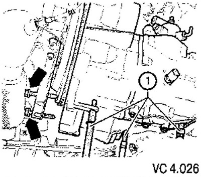
3. Install the gearbox console using new screws (2) (see figure VC4.025).
Tightening torque: 60 Nm + 90°.
4. Move the power unit to the mounting position.
5. Screw the left power unit support with new screws (1).
Tightening torque: 40 Nm + 90°.
6. Screw the right engine support with new screws (arrows) (see figure VC 4.024).
7. Install and tighten the upper transmission-to-engine mounting bolts.
8. Screw the rocker support with new screws (A, B and C) (see figure VC 4.023).
9. Install the flywheel shield (A) behind the right flange of the gearbox (arrows) (see figure VC 4.022).
10. Attach the drive shafts to the gearbox,
11. Secure the front exhaust system bracket to the frame (arrows) (see figure VC 4.021).
12. Connect the exhaust system and straighten it.
13. Install the drive shaft protective cover (arrows) (see figure VC 4.020).
14. Install the starter.
15. Install the wiring bracket (2) and tighten the nut (1) (see figure VC 4.019).
16. Connect the reversing light (3).
17. Tighten the upper starter mounting screw.
18. Connect the ground to the top starter screw (1) (see figure VC 4.018).
19. Connect the connector (2) and cable (3).
20. Install the slave cylinder and tighten the screws (arrows).
21. Install the pipe (A) into the bracket on the gearbox (B).
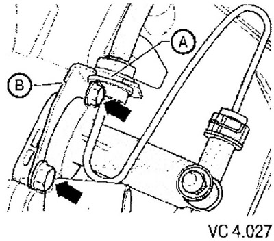
22. Screw the support cable mounting bracket to the gearbox with screws (arrows).
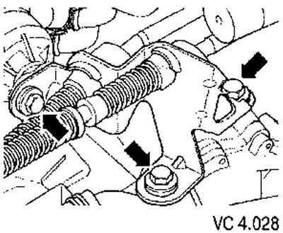
23. Install the gear shift lever (A) and tighten the nut (4).
24. Install the gear selector lever (B) and secure it with the lock washer (3).
25. Lubricate the lever journals.
26. Secure the gear shift cable and gear selector cable with new lock washers (1 and 2, respectively).
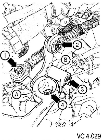
27. Adjust the gear shift mechanism.
28. Check the transmission oil.
29. Install the left fender liner.
30. Install the soundproofing casing under the power unit.
(The information is presented on the website www.vwmanual.ru)
31. Install the battery together with the casing and bracket.
32. Install the assembled air filter housing.
33. Install the engine cover.
Tightening torques depending on engine type
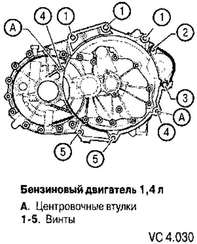
| Pos. | Screw | Quantity | Tightening torque |
| 1 | M12x65 | 3 | 80 Nm |
| 2 | M12x55 | 1 | 80 Nm |
| 3 | M12x170 | 1 | 80 Nm |
| 4 | M12x80 | 2 | 80 Nm |
| 5 | M10x60 | 2 | 40 Nm |
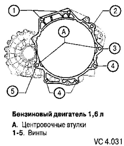
| Pos. | Screw | Quantity | Tightening torque |
| 1 | M12x65 | 2 | 80 Nm |
| 2 | M12x150 | 1 | 80 Nm |
| 3 | M12x170 | 1 | 80 Nm |
| 4 | M12x60 | 3 | 40 Nm |
| 5 | M10x30 | 1 | 80 Nm |
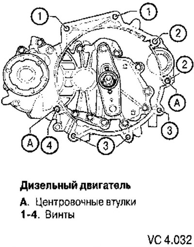
| Pos. | Screw | Quantity | Tightening torque |
| 1 | M12x55 | 2 | 80 Nm |
| 2 | M12x150 | 2 | 80 Nm |
| 3 | M12x60 | 3 | 40 Nm |
| 4 | M12x65 | 1 | 80 Nm |
Visitor comments