
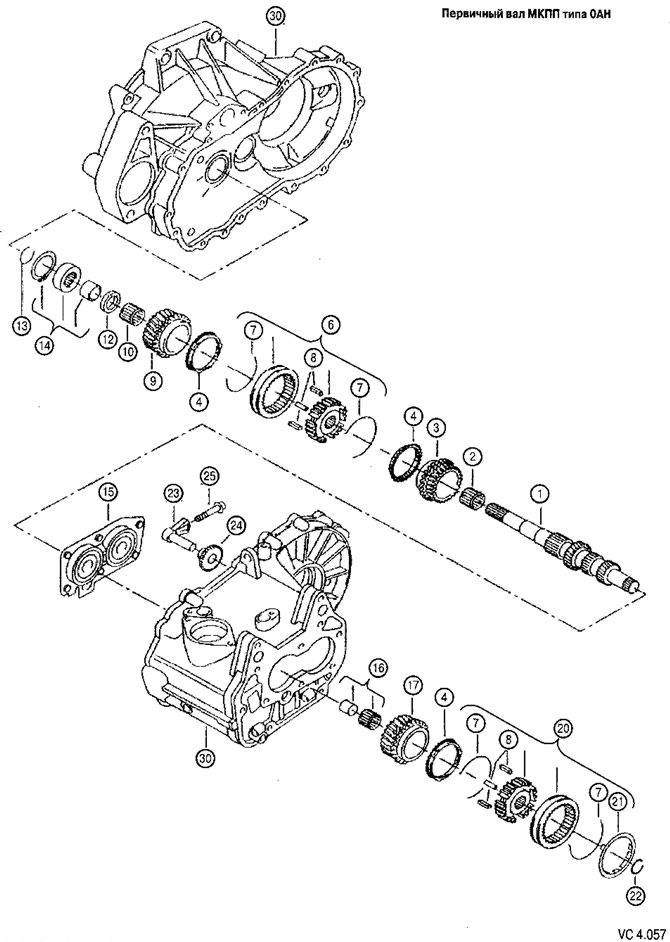
Specification of parts of an assembly unit «input shaft» Manual transmission type 0AH to drawing VC4.057
| Pos. | Detail number | Name | Note (1*) | PC. |
| 1 | 02T311 103K | input shaft | Z=ll+22 FZU, FZT, HFN, GUG | 1 |
| (1) | 02T311 103 T | input shaft | Z=II+22 KBQ | 1 |
| (1) | 02Т311 103Р | input shaft | Z=13+21 GXZ | 1 |
| 2 | 02Т311 265С | Needle cage | 30,5x35,5x26,5 | 1 |
| 3 | 02Т311 129 AJ | 3rd Gear | 41/32 FZU, FZT HFN, GUG, KBQ | 1 |
| (3) | 02T311 129K | 3rd Gear | 43/31 GXZ | 1 |
| 4 | 02Т311 269 V | Synchronizer ring, | 3 | |
| 6 | 02Т311 301 D | Synchronizing clutch for 3rd-4th gears | Use with part 02T 311 269 V | 12 |
| 7 | 02Т311311А | spring | 4 | |
| 7 | 02Т311311А | spring | 4 | |
| 8 | 084311313 | blocking element | 6 | |
| 9 | 02T311 145 R | 4th Gear | 38/41 FZU, FZT, KBQ, HFN | 1 |
| (9) | 02Т311 145 Р | 4th Gear | 40/39 GXZ | 1 |
| (9) | 02T311145 AK | 4th Gear | 38/41 GUG | 1 |
| 10 | 02T311 132A | Needle bearing | 24,3x35,5x26,3 | 1 |
| 12 | 02T311 155A | Washer, thrust | 24x42x3 | 1 |
| 13 | 02T311327 | Thrust ring | 21,8x27x2 | 1 |
| 14 | 02T311 375 E | Roller bearing without inner ring | 24,1x47x17,7 | 1 |
| 15 | ||||
| 16 | 085 311431 C | Needle bearing | 1 | |
| 17 | 02T311 158 R | 5th Gear | 37/50 FZU, FZT, KBQ, HFN | 1 |
| (17) | 02Т311 158 N | 5th Gear | 39/48 GXZ | 1 |
| (17) | 02T311 158 AK | 5th Gear | 37/50 GUG | 1 |
| 20 | 02Т311241А | 5th gear synchro clutch | 1 | |
| 21 | 020311331 B | Thrust ring | 1 | |
| 22 | 085311 187 | Thrust ring | 17,7x2 | |
| (22) | 085311 187 A | Thrust ring | 17,7x2,1 | |
| (22) | 085311 187 V | Thrust ring | 17,7x2,2 | |
| 23 | 02Т311 503С | reverse gear axle | 1 | |
| 24 | 02T 311 529V | Reverse gear | Z=24 FZU, FZT GXZ, HFN, GUG | 1 |
| (24) | 02Т311 529С | Reverse gear | Z=24 KBQ | 1 |
| 25 | 910437 01 | Screw with internal polyhedron | M8x40 | 1 |
| 30 | Gearbox housing |
(1*) This column shows the number of teeth on the input shaft, the gear ratios of the 3rd, 4th and 5th gear pairs, and the letter designations of the gearbox in which these parts are used.
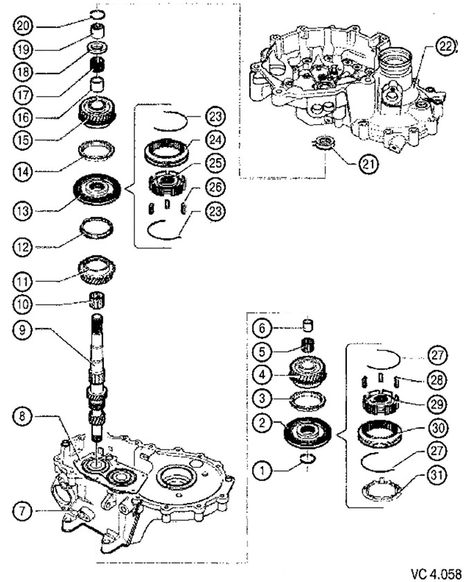
List of assembly unit parts «input shaft» with technological notes to figure VC4.058:
1. Thrust ring (be sure to replace).
2. 5th gear sliding clutch hub.
3. 5th gear synchronizer blocking ring.
4. 5th gear synchronizer clutch.
5. Needle bearing (replaced with bushing).
V. Sleeve (replaced with needle bearing).
7. Gearbox housing.
8. Bracket with deep groove ball bearing (when removing from the crankcase, the gearbox must be replaced; when replacing the ball bearing, be sure to replace the bracket).
9. Primary shaft.
10. Needle bearing.
11. 3rd gear synchronizer clutch.
12. Blocking ring of the synchronizer of 3rd transfer.
13. Hub with sliding clutch synchronizer 3rd and 4th gear.
14. Blocking ring of the synchronizer of 4th transfer.
15. 4th gear synchronizer clutch.
16. Sleeve (replaced with needle bearing).
17. Needle bearing (replaced with bushing).
18. Thrust washer.
19. Cylindrical bearing inner ring.
20. Blocking ring (replace with a new one).
21. Cylindrical rolling bearing with blocking ring (Installation Position: Bearing Locking Ring Input Shaft Side).
22. Clutch housing.
23. Spring.
24. Sliding clutch of the synchronizer of 3rd and 4th gears.
25. Synchronizer hub for 3rd and 4th gears.
26. Crackers (3 pcs.).
27. Spring.
28. Crackers (3 pcs.).
29. Synchronizer hub 5th gear.
30. 5th gear synchronizer sliding clutch.
31. Blocking ring.
Visitor comments