
Attention: When the cardan shaft is dismantled, the car must not rest on the wheels with its entire mass, since in the absence of axial preload, the hub bearing is damaged. If necessary, replace the cardan shaft with an external joint shank and tighten the fastener to 50 Nm.
Disassembly
Remove cardan shaft see relevant chapter.
Cut the fastening clamps of the corrugated covers on both hinges with wire cutters and remove. Slide the corrugated covers onto the shaft.
Clamp the cardan shaft in a vise with aluminum protective jaws.
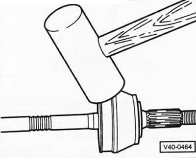
External constant velocity joint: knock the joint off the shaft with strong blows of a plastic hammer.
Remove circlip -16- from joint, see figure S40-0255.
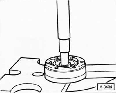
Internal CV joint: Use a suitable rod to knock the protective cap off the joint.
Internal constant velocity joint: remove the circlip with suitable pliers, eg VAG-161a or HAZET 2525K.
Remove the inner joint using a suitable press, while supporting the inner joint hub. Remove the bellows, belleville spring, and joint seal from the shaft.
Assembly
Replace fragile or defective bellows.
To put on a shaft a corrugated cover with a collar for the internal hinge.
Inner and outer joints: Fill the new joint with high-temperature grease, eg G 000 603 from VW. For a new joint, place half of the amount of grease in the bellows and press the other half into the joint. If only the bellows are to be replaced, the joint must only be refilled with grease if necessary.
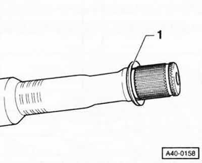
Inner constant velocity joint: Fit disc spring -1- onto propshaft. In this case, the belleville spring should be correctly installed: its large diameter rests on the hinge.
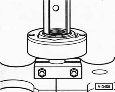
Using a suitable press, press the inner joint to the stop.
Note: Chamfer on inner diameter of pivot hub (at splines) must face the support shoulder of the cardan shaft. Using suitable pliers, for example, VW-161a or HAZET 2525K, install a new circlip into the annular groove of the shaft.
To put on a shaft together with a collar a corrugated cover for the external hinge.
Install the bellows in the installation position.
Attention: The cover often shrinks when installed on the hinge body. As a result, under the cover there is a rarefaction of air, which during operation draws the cover inside. Therefore, after mounting the cover, you need to slightly lift its edge with a screwdriver on the side of the small diameter and thereby ensure pressure equalization.
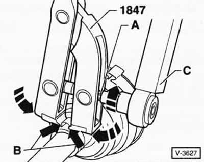
For tightening clamps (alloy steel) special pliers must be used, eg HAZET 1847, otherwise the required tightening force will not be achieved. Attach the pliers, as shown in the figure, with the teeth to the corners of the clamp -arrows B-. In this position, use a torque wrench to tighten bolt -A- to 20 Nm. The tightening of the clamp on the small diameter of the corrugated cover is performed in a similar way.
Attention: The thread of the pliers must be easy to move and, if necessary, pretreated with MoS grease2.
Internal CV joint: Glue a new seal to the joint after removing the protective film from it.
Install the propeller shaft see relevant chapter.

Visitor comments