
English Русский
Български
Беларускі
Український
Српски
Hrvatski
Română
Polski
Slovenský
Magyar
  |  Articles  |  Sitemap  |  Contacts  |    |
Car maintenance Ford Car maintenance Hyundai Car maintenance Chevrolet Car maintenance BMW Car maintenance Audi Car maintenance Opel Car maintenance AvtoVAZ
VWmanual.ru


Main   Passat   Golf   Polo   Touareg   Tiguan   Sharan   Transporter   Others  
Passat B2 (1981-1988) Passat B3 (1988-1993) Passat B4 (1988-1996) Passat B5 (1996-2005) Passat B6 (2005-2010)

Removal and installation the propeller shaft (VW Passat B3)

  • Main
  • Passat
  • Passat B3
  • Chassis
  • Suspension
  • Removal and installation the propeller shaft
            0


Contents: Removal ↓ Installation ↓ Positive running gear ↓
Note: The vehicle must not be moved when the cardan shaft is removed, as the hub bearing will be damaged if there is no axial pressure. If necessary, install an outer joint instead of the cardan shaft.


When replacing the propeller shaft, move the vibration damper to the new shaft. Note: On cars with a 4-cylinder engine and automatic transmission since 2/94, propeller shafts with constant velocity joints "Tripod" are installed. To remove the left propeller shaft, it is necessary to hang the engine and release its supports. The inner propeller joint can only be replaced together with the propeller shaft.

Removal


Loosen the nut securing the wheel hub to the propeller shaft.

Caution: The car must be on its wheels. Risk of accident!


Basic chassis: remove washer.

Loosen the wheel bolts and raise the vehicle.

Remove the wheel.

Remove the internal joint bolts with internal slots on the head. To do this, use a key with a replaceable socket head with external slots, for example, HAZET 990 Lg-8.
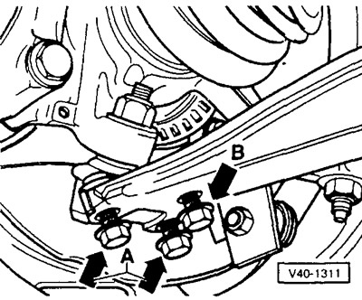
Remove the internal joint bolts with internal slots on the head. To do this, use a key with a…


Mark the relative positions of the ball joint and the wishbone by tracing the heads of the mounting bolts with a scriber.


Basic chassis: unscrew the mounting bolts (arrows).

Positive chassis: first remove bolts "A", then bolt "B".

Separate the ball joint from the wishbone.

If you can't pull the driveshaft out manually, press it out of the wheel hub with a suitable puller. The VW workshop uses the VW-3283 puller for this.

Tilt the shock absorber strut outward and remove the drive shaft from the wheel hub bearing housing.

If the cardan shaft is being replaced, remove the vibration damper. To do this, knock out the clamping sleeve and separate the 2 halves of the damper.

Note: From 8/89 to 9/93, non-detachable dampers were installed. To remove, it is necessary to first press out the inner constant velocity cardan joint, and then the damper.


Installation


If it was removed, put the vibration damper back in place and drive in a new clamping sleeve. Note: When doing this, close the shaft so as not to damage the protective packing coating when driving in. Before installing, check the effectiveness of the adhesive tape on the inner diameter of the damper. If necessary, replace the adhesive tape or apply another adhesive. The adhesive tape prevents the possibility of axial movement of the damper along the cardan shaft.

Installation dimensions for vibration damper (all models):
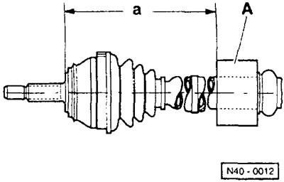
Installation dimensions for vibration damper (all models):


Right cardan shaft: a = 521 ±1 mm; left cardan shaft (if the damper is installed): a = 264 ±1 mm.


Note: For vehicles manufactured prior to 10/88, see instructions at end of section.


Before installation, clean the driveshaft splines with gasoline to remove oil and grease, and remove all deposits from the protective coating.

Positive chassis:
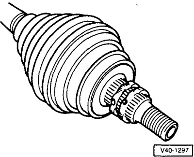
Positive chassis:


Up to about 12/94: Apply liquid protective agent from VW D185400A2 to the splines as shown in the picture. The cross-section of the protective agent layer is about 3 mm.

Note: Since about 12/94 a modified wheel hub has been installed, the spline tips of which are slightly compressed. The new hub can also be installed on earlier cars. If such a hub is installed, no protective agent is required.
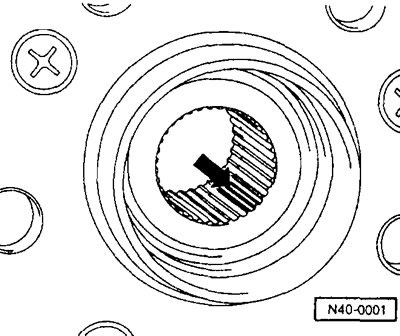

Note: Since about 12/94 a modified wheel hub has been installed, the spline tips of which are…


Insert the cardan shaft into the wheel hub and secure it with the old nut. Tighten the nut until the outer hinge axle enters the hub as far as it will go. Do not tighten the nut.

Tighten the ball joint to the wishbone with a torque of 35 Nm, making sure that the bolts are positioned in accordance with the previously applied marks.

Screw the cardan shaft to the gearbox output shaft flange.

Screw in the bolts with internal slots on the head that secure the inner joint and tighten them crosswise to a torque of 45 Nm. Do not forget to put locking washers under the 6omJ.

Positive running gear


From about 12/94 or cars with new wheel hub:


Loosen the nut securing the wheel hub to the propeller shaft.

Lubricate the contact surfaces of the new 12-sided nut with oil and tighten it as far as possible.

Lower the car. Make sure that the wheels do not touch the floor yet, otherwise the hub bearing may be damaged.

Apply the brakes (need an assistant).
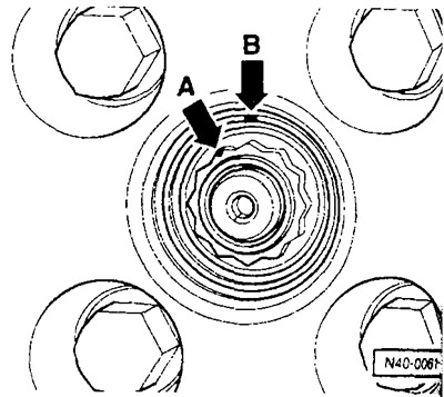
Apply the brakes (need an assistant).


tighten the 12-sided nut to a torque of 200 Nm, then release it one turn.

Tighten the 12-point nut to 50 Nm.

Mark the top of the 12-sided nut with a scriber (arrow A, Fig. No.40-006).

Place the second mark (arrow B) on the edge of the wheel hub opposite the next 12-sided nut vertex.

Note: The angle between two adjacent vertices of a 12-sided figure is 30°.


Tighten the 12-sided nut to the specified angle until the marks match.

Install the front wheel, setting it in its previous position relative to the mark on the hub, lower the car and tighten the wheel bolts in a crosswise manner to a torque of 110 Nm.

Basic chassis: unscrew the nut securing the hub to the driveshaft and install a new self-locking nut, tightening it to a torque of 265 Nm. Do not forget to install the lining washer.

View the original on this resource (vwmanual.ru)

Positive chassis up to approximately 12/94: Loosen the nut securing the hub to the propeller shaft and install a new self-locking 12-point nut. Tighten the nut to 90 Nm and turn it an additional 1/8 of a turn (45°). Caution: Tighten the handbrake. Ask an assistant to apply the foot brake. The vehicle must stand on its wheels when tightening. Risk of accident!

Install the wheel cover.

Check wheel alignment if necessary (workshop work).

This article is available at russian, bulgarian, belarusian, ukrainian, serbian, croatian, romanian, polish, slovak, hungarian
The text has been checked: Medvedeva Elena

Share information:

Previous articles
Removal and installation the shock absorber / disassembling the shock absorber strut
Shock absorber strut device
Removal and installation the front shock absorber strut
Front suspension device
Front axle design
Next articles
Cardan shaft device
Disassembly and assembly of the cardan shaft
Visual inspection of the front wheel suspension
General information about the rear axle
Rear shock absorber strut device
Removal and installation / disassembly of the rear shock absorber strut


Similar articles from other manuals for VW cars:
Auxiliary shaft seal Golf 1 (1974-1984, petrol)
Removal and installation the propeller shaft Polo 4 (2001-2009)
Replacing the PTO/Front Propeller Shaft Flange Seal (Transfer… Touareg 1 (2002-2006)
Removal and installation the propeller shaft Tiguan 1 (2007-2015)
Intermediate shaft — removal and installation Sharan 1 (1995-2000)
Speedometer shaft — removal and installation Transporter T4 (1990-2003)
Propeller shaft — removal and installation (models with 2.4l… LT 28 (1975-1991)
Link to this page in different formats


Visitor comments


No comments yet


How much will 28 + 40 =


Passat B6 
  • General information
  • User manual
  • Maintenance
  • Petrol engine 1.6L
  • Engine repair
  • Cooling and lubrication system
  • Fuel injection system
  • Petrol engine 2.0L
  • Engine repair
  • Lubrication system
  • Cooling system
  • Fuel and exhaust systems
  • Diesel engine 2.0L
  • Engine repair
  • Cooling and lubrication system
  • Fuel and exhaust systems
  • Transmission
  • Clutch
  • Mechanical gearbox
  • Automatic gearbox
  • Drive shafts
  • Chassis
  • Wheels and tires
  • Car suspension
  • Steering
  • Brake system
  • Body
  • Exterior (external elements)
  • Electrical equipment
  • Power devices
  • Lighting and appliances
  • Electrical circuits
Passat B5 
  • General information
  • User manual
  • Weekly checks
  • Maintenance
  • Power unit
  • Engine repair
  • Cooling system
  • Fuel system (petrol)
  • Fuel system (diesel)
  • Engine management
  • Exhaust system
  • Transmission
  • Clutch
  • Car gearbox
  • Drive shafts
  • Chassis
  • Car suspension
  • Wheels and tires
  • Steering
  • Brake system
  • Body
  • Exterior (external elements)
  • Interior (internal elements)
  • Doors and covers
  • Ventilation and heating
  • Electrical equipment
  • Power devices
  • Lighting and appliances
  • Electrical circuits
Passat B4 
  • General information
  • User manual
  • Maintenance
  • Technical data
  • 8-valve engine
  • Engine repair
  • Cooling and lubrication system
  • Supply system
  • Ignition system
  • Fuel injection «Mono-Jetronic»
  • Control system «Mono-Motronic»
  • Control system «Digifant»
  • Control system «Simos»
  • 16-valve engine
  • Engine repair
  • Cooling and lubrication system
  • Fuel injection «K-Jetronic»
  • Control system «KE-Motronic»
  • Control system «Digifant»
  • Diesel engine
  • Engine repair
  • Cooling and lubrication system
  • Power and control system
  • Turbocharging system
  • Digital control system
  • Transmission
  • Clutch
  • Manual gearbox
  • Hydromechanical gearbox
  • Front wheel drive
  • Chassis
  • Car suspension
  • Steering
  • Brake system
  • Body
  • Body elements
  • Electrical equipment
  • Power devices
  • Lighting and appliances
  • Electrical circuits
Passat B3 
  • General information
  • User manual
  • Driving Tips
  • Maintenance instructions
  • Technical data
  • Power unit
  • Engine repair
  • Ignition system
  • Lubrication system
  • Cooling system
  • Supply system
  • Petrol injection system
  • Diesel engine
  • Exhaust system
  • Transmission
  • Clutch
  • Car gearbox
  • Chassis
  • Suspension
  • Steering
  • Brake system
  • Wheels and tires
  • Body
  • Exterior
  • Interior
  • Heating system
  • Electrical equipment
  • Power devices
  • Lighting system
  • Equipment and devices
  • Wiper system
  • Electrical circuits
Passat B2 
  • General information
  • Introduction to instructions
  • User manual
  • Power unit
  • Engines 4-cylinder FZ
  • Engines 4-cylinder
  • Engines 5-cylinder
  • Transmission
  • Clutch
  • Four-speed gearbox
  • Five-speed gearbox
  • Hydromechanical gearbox
  • Front wheel drive
  • Chassis
  • Front suspension
  • Rear suspension
  • Steering
  • Brake system
  • Body
  • Body elements
  • Electrical equipment
  • Equipment and devices
  • Electrical circuits
VWmanual.ru © 2016-2026 | Mobile version | News and articles | Sitemap: EN BG BY UA RS HR RO PL SK HU | Write message | Site search
Passat B2 • Passat B3 • Passat B4 • Passat B5 • Passat B6 • Golf 1, diesel • Golf 1, petrol • Golf 2, petrol • Golf 2 • Golf 3 • Golf 4 • Golf 5 • Polo 3 • Polo 4 • Touareg 1 • Tiguan 1 • Sharan 1 • Transporter T3 • Transporter T4 • LT 28 • LT 2D • Beetle • Caddy 3 •
Our website uses cookies to ensure functionality and convenience.