English Русский
Български
Беларускі
Український
Српски
Hrvatski
Română
Polski
Slovenský
Magyar
  |  Articles  |  Sitemap  |  Contacts  |    |
Car maintenance Ford Car maintenance Hyundai Car maintenance Chevrolet Car maintenance BMW Car maintenance Audi Car maintenance Opel Car maintenance AvtoVAZ
VWmanual.ru


Main   Passat   Golf   Polo   Touareg   Tiguan   Sharan   Transporter   Others  
Passat B2 (1981-1988) Passat B3 (1988-1993) Passat B4 (1988-1996) Passat B5 (1996-2005) Passat B6 (2005-2010)

Disassembly and assembly of the cardan shaft (VW Passat B3)

  • Main
  • Passat
  • Passat B3
  • Chassis
  • Suspension
  • Disassembly and assembly of the cardan shaft
            0


Contents: General instructions ↓ Disassembly ↓ Assembly ↓

General instructions


Replace defective corrugated boots immediately. To replace the boots, the cardan shaft must be disassembled. If dirt has penetrated the grease, wash the joint and fill it with new G6 grease. A defect in the joint balls is recognized by the impact change in load when switching to engine braking mode and by clicking noises. In this case, replace the joint as a set.

Attention: When the cardan shaft is removed, the vehicle must not be moved, since the lack of axial pressure will damage the hub bearing.


Disassembly


Remove the propeller shaft.
Cut the clamps on both hinges with nippers and remove. Move the hinge covers back.
Cut the clamps on both hinges with nippers and remove. Move the hinge covers back.


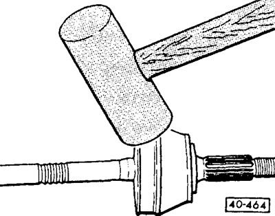
Outer joint: Knock the joint off the drive shaft with strong blows from a light alloy hammer.
Outer joint: Knock the joint off the drive shaft with strong blows from a light alloy hammer.


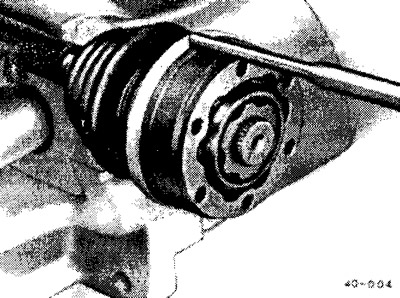
Inner joint: Knock the protective cap off the joint with a suitable rod.


Inner joint: Knock the protective cap off the joint with a suitable rod.


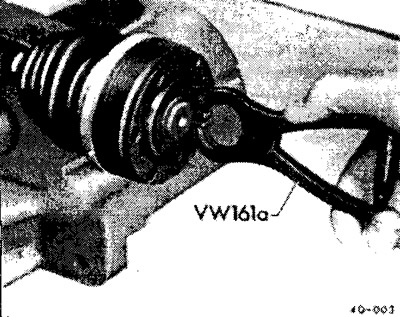
Inner joint: remove the retaining ring with suitable pliers, e.g. VW-161 a or HAZET 2525K.
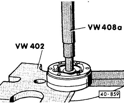
Inner joint: remove the retaining ring with suitable pliers, e.g. VW-161 a or HAZET 2525K.


Remove the inner joint using a suitable press. Support the joint hub while doing so.

Remove the disc spring and corrugated boot from the drive shaft.

Inner joint: On vehicles with engines over 90 hp and all models with 10/93, remove the additional sealing gasket.

Assembly


Replace fragile or defective covers.

Place the cover with the clamp for the inner joint on the shaft.
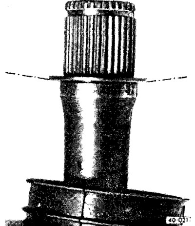
Place the cover with the clamp for the inner joint on the shaft.


Inner joint: place the disc spring on the cardan shaft. The disc spring must be installed correctly: its large diameter rests on the joint.


Inner joint: fill the new joint with 110 g of G6 grease. Distribute the grease equally between the joint and the bellows. If only the bellows is being replaced, only add grease to the joint.
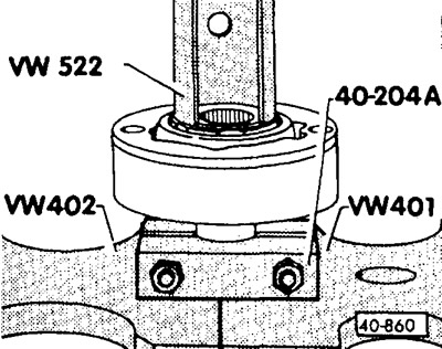
Inner joint: fill the new joint with 110 g of G6 grease. Distribute the grease equally between the…


The inner joint is pressed in until it stops using a suitable press.

Note: Chamfer on the inner diameter of the joint hub (toothed ring) must be facing the support flange of the cardan shaft.


Install a new retaining ring into the shaft groove using suitable pliers, such as VW-161a or HAZET 2525.

Vehicles with engines from 90 hp and all models from 10/93: indicate the installation dimension for the corrugated cover.

Before installing the corrugated cover on the cardan shaft, mark the installation position with paint or adhesive tape. Do not use: a scriber, and do not damage the protective varnish with any other sharp object.
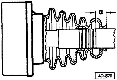
Before installing the corrugated cover on the cardan shaft, mark the installation position with…


Left propeller shaft: size a = 17mm

Left propeller shaft: size a = 17mm


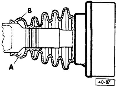
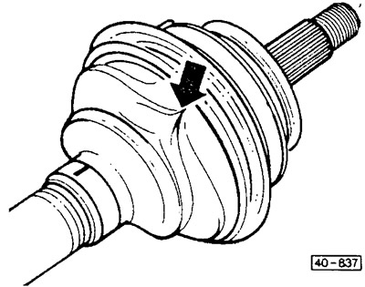
Right cardan shaft: The large diameter ventilation chamber "A" must be placed on the large diameter shaft pipe. B is the ventilation hole.

Inner joint: Lubricate the clean end of the joint boot cap with VAG-D3 repmetic. Put the cap on the joint body.

Place the corrugated outer joint boot onto the shaft together with the clamp and collar.

Outer hinge: fill the new hinge with 110 g of G6 grease. Spread the grease equally between the hinge and the bellows. If you are replacing only the bellows, only add grease to the hinge.
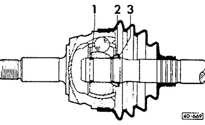
Outer hinge: fill the new hinge with 110 g of G6 grease. Spread the grease equally between the…


Place the disk spring "3" and the spacer washer "2" on the cardan shaft. In this case, the disk spring must be installed correctly: its large diameter rests on the spacer washer. The spherical surface of the spacer washer faces the hinge.

Insert a new retaining ring into the groove of the shaft. Drive the retaining ring onto the shaft with a rubber hammer until it locks into the groove.

The constant velocity cardan joint is placed on the shaft using blows from a plastic or light metal hammer.
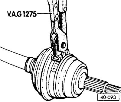
The constant velocity cardan joint is placed on the shaft using blows from a plastic or light metal…


Place the corrugated cover in the correct position and secure it with a clamp.
with a clamp.


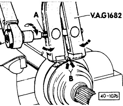
1.6 l petrol engine and turbocharged diesel engines: improved bellows are installed on the outer joints of the cardan shafts of vehicles with these engines from 1/90. Due to the more durable material of the bellows, new clamps made of alloy steel are also installed. These clamps can no longer be tightened with the previous VAG 1275 pliers. The pliers shown in the figure must be used. The cutting edges of the pliers must rest against the corners (arrows B) of the clamp. In this position, tighten bolt "A" with a torque wrench to 25 Nm and thus tighten the clamp. Tightening the clamp on the small diameter of the bellows is carried out in a similar manner.
1.6 l petrol engine and turbocharged diesel engines: improved bellows are installed on the outer…


Note: When installing the cover on the hinge body, it often gets compressed. As a result, a vacuum of air appears under the cover, which pulls the cover inward during operation. Therefore, after installing the cover, you need to slightly lift its edge on the small diameter side with a screwdriver to equalize the pressure.


Inner joint: On vehicles with engines over 90 hp and on all models with 10/93, glue a new sealing gasket into the joint, having first removed the protective film from it.

This article is available at russian, bulgarian, belarusian, ukrainian, serbian, croatian, romanian, polish, slovak, hungarian
The text has been checked: Medvedeva Elena

Share information:

Previous articles
Cardan shaft device
Removal and installation the propeller shaft
Removal and installation the shock absorber / disassembling the shock absorber strut
Shock absorber strut device
Removal and installation the front shock absorber strut
Front suspension device
Next articles
Visual inspection of the front wheel suspension
General information about the rear axle
Rear shock absorber strut device
Removal and installation / disassembly of the rear shock absorber strut
Wheel with drum brake mechanism
Removal and installation the rear wheel hub bearing


Similar articles from other manuals for VW cars:
Auxiliary shaft seal Golf 1 (1974-1984, petrol)
Cardan shaft/cardan shaft bellows/constant velocity joints Polo 4 (2001-2009)
Removal and installation sealing rings of the PTO/cardan shaft… Touareg 1 (2002-2006)
Cardan shaft device Tiguan 1 (2007-2015)
Intermediate shaft — removal and installation Sharan 1 (1995-2000)
Dismantling and installation of the cardan shaft Transporter T3 (1979-1992)
Cardan shaft specifications and description LT 28 (1975-1991)
Link to this page in different formats


Visitor comments


No comments yet


How much will 42 + 28 =


Passat B6 
  • General information
  • User manual
  • Maintenance
  • Petrol engine 1.6L
  • Engine repair
  • Cooling and lubrication system
  • Fuel injection system
  • Petrol engine 2.0L
  • Engine repair
  • Lubrication system
  • Cooling system
  • Fuel and exhaust systems
  • Diesel engine 2.0L
  • Engine repair
  • Cooling and lubrication system
  • Fuel and exhaust systems
  • Transmission
  • Clutch
  • Mechanical gearbox
  • Automatic gearbox
  • Drive shafts
  • Chassis
  • Wheels and tires
  • Car suspension
  • Steering
  • Brake system
  • Body
  • Exterior (external elements)
  • Electrical equipment
  • Power devices
  • Lighting and appliances
  • Electrical circuits
Passat B5 
  • General information
  • User manual
  • Weekly checks
  • Maintenance
  • Power unit
  • Engine repair
  • Cooling system
  • Fuel system (petrol)
  • Fuel system (diesel)
  • Engine management
  • Exhaust system
  • Transmission
  • Clutch
  • Car gearbox
  • Drive shafts
  • Chassis
  • Car suspension
  • Wheels and tires
  • Steering
  • Brake system
  • Body
  • Exterior (external elements)
  • Interior (internal elements)
  • Doors and covers
  • Ventilation and heating
  • Electrical equipment
  • Power devices
  • Lighting and appliances
  • Electrical circuits
Passat B4 
  • General information
  • User manual
  • Maintenance
  • Technical data
  • 8-valve engine
  • Engine repair
  • Cooling and lubrication system
  • Supply system
  • Ignition system
  • Fuel injection «Mono-Jetronic»
  • Control system «Mono-Motronic»
  • Control system «Digifant»
  • Control system «Simos»
  • 16-valve engine
  • Engine repair
  • Cooling and lubrication system
  • Fuel injection «K-Jetronic»
  • Control system «KE-Motronic»
  • Control system «Digifant»
  • Diesel engine
  • Engine repair
  • Cooling and lubrication system
  • Power and control system
  • Turbocharging system
  • Digital control system
  • Transmission
  • Clutch
  • Manual gearbox
  • Hydromechanical gearbox
  • Front wheel drive
  • Chassis
  • Car suspension
  • Steering
  • Brake system
  • Body
  • Body elements
  • Electrical equipment
  • Power devices
  • Lighting and appliances
  • Electrical circuits
Passat B3 
  • General information
  • User manual
  • Driving Tips
  • Maintenance instructions
  • Technical data
  • Power unit
  • Engine repair
  • Ignition system
  • Lubrication system
  • Cooling system
  • Supply system
  • Petrol injection system
  • Diesel engine
  • Exhaust system
  • Transmission
  • Clutch
  • Car gearbox
  • Chassis
  • Suspension
  • Steering
  • Brake system
  • Wheels and tires
  • Body
  • Exterior
  • Interior
  • Heating system
  • Electrical equipment
  • Power devices
  • Lighting system
  • Equipment and devices
  • Wiper system
  • Electrical circuits
Passat B2 
  • General information
  • Introduction to instructions
  • User manual
  • Power unit
  • Engines 4-cylinder FZ
  • Engines 4-cylinder
  • Engines 5-cylinder
  • Transmission
  • Clutch
  • Four-speed gearbox
  • Five-speed gearbox
  • Hydromechanical gearbox
  • Front wheel drive
  • Chassis
  • Front suspension
  • Rear suspension
  • Steering
  • Brake system
  • Body
  • Body elements
  • Electrical equipment
  • Equipment and devices
  • Electrical circuits
VWmanual.ru © 2016-2026 | Mobile version | News and articles | Sitemap: EN BG BY UA RS HR RO PL SK HU | Write message | Site search
Passat B2 • Passat B3 • Passat B4 • Passat B5 • Passat B6 • Golf 1, diesel • Golf 1, petrol • Golf 2, petrol • Golf 2 • Golf 3 • Golf 4 • Golf 5 • Polo 3 • Polo 4 • Touareg 1 • Tiguan 1 • Sharan 1 • Transporter T3 • Transporter T4 • LT 28 • LT 2D • Beetle • Caddy 3 •
Our website uses cookies to ensure functionality and convenience.