
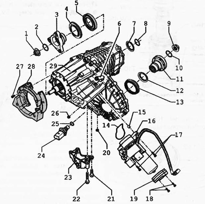
Pic. 3.107. Transfer case components:
1 - nut, 130 Nm; 2 - O-ring; 3 - flange of the power take-off shaft; 4 - metal anther; 5 - sealing ring; 6 - ventilation tube; 7 - sealing ring of the input shaft; 8 - O-ring; 9 - nut, 130 Nm; 10 - O-ring; 11 - flange of the power take-off shaft; 12 - metal anther; 13 - sealing ring; 14 - O-ring; 15 - mounting sleeve; 16 - electric motor of the transfer case; 17 - bolt, 27 Nm; 18 - bolt, 14 Nm; 19 - clamp; 20 - oil drain plug, 20 Nm; 21 - bolt, 20 Nm; 22 - bolt, 20 Nm; 23 - console; 24 - oil temperature sensor, 17 Nm; 25 - sealing ring; 26 - bolt holes for oil filling, 20 Nm; 27 - bolt, 32 Nm; 28 - damper; 29 - transfer box.
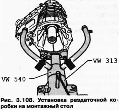
Attach the transfer case to the mounting stand with bolts (pic. 3.108).
Press out the metal boot (pic. 3.109).
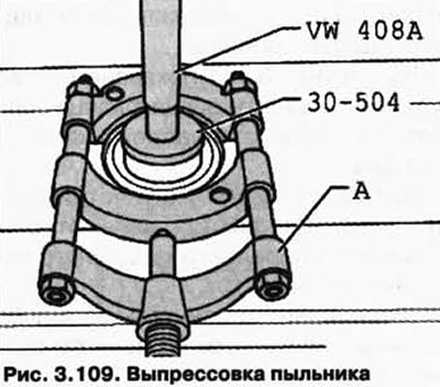
A - Puller 22-115 mm, e.g. Kukko 17/2.
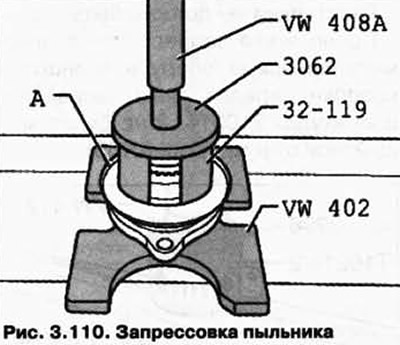
Press the metal boot A to the stop (pic. 3.110).
Remove the PTO/rear propshaft flange O-ring.
Figure 3.111 shows the removal of the PTO/rear propshaft flange O-ring.
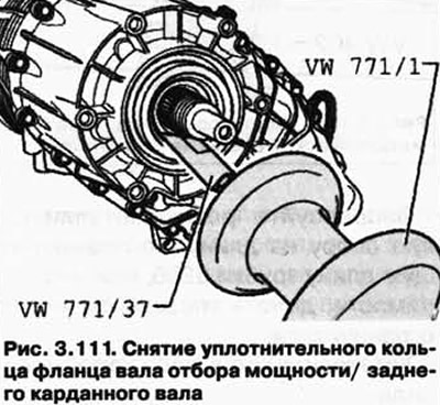
The procedure for removing the PTO/Front PTO flange O-ring is similar.
Press in the O-ring of the PTO flange/rear propeller shaft (pic. 3.112).
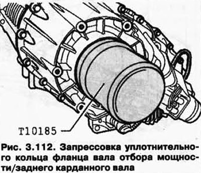
Fill the space between the sealing lips and dust seal halfway with grease G 052 128 A1.
Install the O-ring into the groove of the input shaft.
Press the metal boot A to the stop (pic. 3.110).
Press in the O-ring on the PTO/Front PTO flange.
Fill the space between the sealing and dust sealing lips halfway with grease G 052 128 A (pic. 3.112).
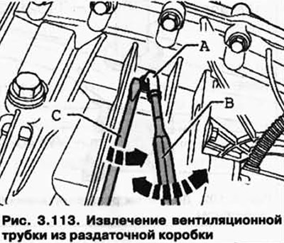
Remove vent tube A.
Insert mandrel B with ∅ 5 mm into the opening of the ventilation tube.
Move the vent tube A in the direction of the arrow, at the same time lift it up with a screwdriver C and remove the vent tube from the transfer case (pic. 3.113).
Press in the ventilation tube (pic. 3.114).
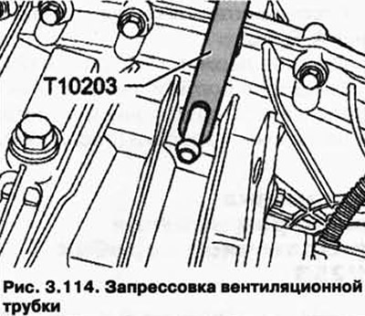
Lubricate the ventilation tube with Loctite 648 fixing varnish before pressing it in.
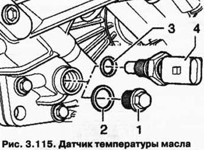
Repair method when replacing the transfer case motor V253 and with a faulty oil temperature sensor G8.
When replacing the transfer case motor V253 and if the oil temperature sensor 4 is faulty, the oil temperature sensor must be replaced (with o-ring 3) through screw plug 1 with O-ring 2 (pic. 3.115).
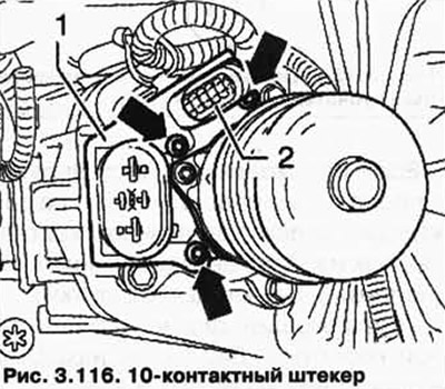
Disassembly of the G8 oil temperature sensor wiring harness is carried out in the following order.
Remove the holder 1 of the transfer box electric motor plug, to do this, unscrew the bolts.
Remove the 10-pin plug 2 from the holder (pic. 3.116).
Remove wires 1 and 2 of the 10-pin plug using a suitable tool from the VAS 1978 cable repair kit.
Disconnect wiring harness 3 oil temperature sensor (pic. 3.117).
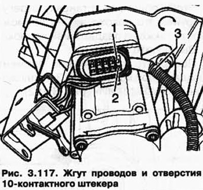
Close the wire openings of the 10-pin plug 1 and 2 with a suitable plug.
Visitor comments