



Contents: Removal ↓ Installation ↓
Constant velocity ball joint drive shaft
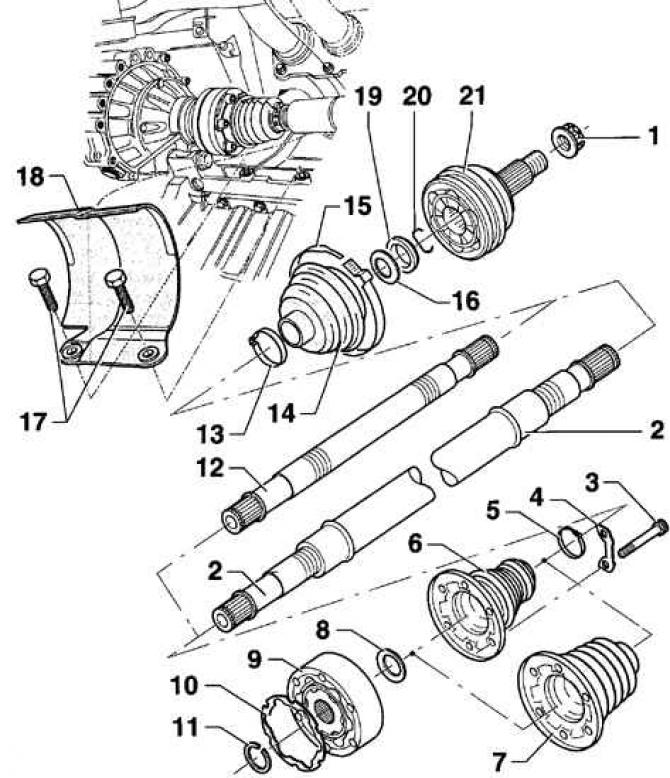
- 1 - Self-locking twelve-sided nut. A new nut must be used during installation;
- 2 - right drive shaft;
- 3 - bolt with internal shaped recess, 40 Nm;
- 4 - plate;
- 5 - clamp;
- 6 - protective cover. The inner cuff is made of plastic without ventilation holes;
- 7 - internal protective shell of the hinge. The internal cuff is made of rubber with a hole for ventilation;
- 8 - disc spring;
- 9 - internal constant velocity joint. The joint can only be replaced as an assembly;
- 10 - Seal. When installing, it is necessary to use a new seal. Remove the protective film from the seal and glue the seal to the hinge;
- 11 - retaining ring;
- 12 - left drive shaft;
- 13 - clamp;
- 14 - outer hinge protective cover;
- 15 - clamp;
- 16 - disc spring;
- 17 - bolt, 35 Nm;
- 18 - protective cover;
- 19 - thrust ring;
- 20 - retaining ring;
- 21 - external constant velocity joint
Drive shaft with three-arm joint (Tripod)
(The information is presented on the website: «VWmanual.ru»)
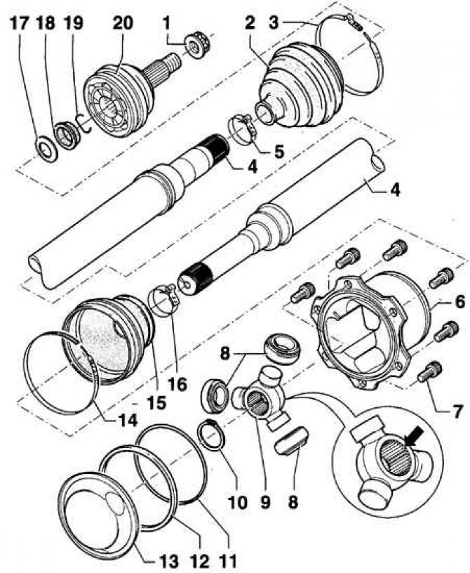
- 1 - Self-locking twelve-sided nut. A new nut must be used during installation;
- 2 - protective cover of the outer hinge;
- 3 - clamp;
- 4 - drive shaft;
- 5 - clamp;
- 6 - hinge housing;
- 7 - bolt with internal shaped recess, 40 Nm;
- 8 - roller;
- 9 - three-arm roller holder. The chamfer on the roller holder splines should be directed towards the drive shaft;
- 10 - retaining ring. A new retaining ring must be used when installing;
- 11 - O-ring round section. If there is damage, a new O-ring must be used;
- 12 - sealing ring;
- 13 - lid;
- 14 - large clamp;
- 15 - Inner hinge protective cover;
- 16 - small clamp;
- 17 - disc spring;
- 18 - thrust ring;
- 19 - retaining ring;
- 20 - inner constant velocity joint. Should it fail, it must be replaced. When installing on the drive shaft, press the CV joint with a plastic hammer until it is secured with a retaining ring
Warning: After removing the drive shaft from the vehicle, do not lower the vehicle to the ground or move it, otherwise the hub bearing may be easily damaged.
Removal
1. Raise the vehicle and remove the front wheel.
2. Unscrew the twelve-sided nut securing the drive shaft to the hub. To keep the hub from turning while unscrewing the nut, have an assistant press the brake pedal.
3. Remove the socket head cap screws securing the drive shaft to the gearbox flange. You can use an internal multi-tooth wrench, such as the HZ 990 Lg-8, to remove the bolts.
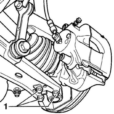
4. Using a scriber, mark the installation position of the bolts (1) securing the lower ball joint of the front suspension to the wishbone. Unscrew the bolts.
5. Tilt the shock absorber outward from the vehicle and remove the drive shaft from the steering knuckle.
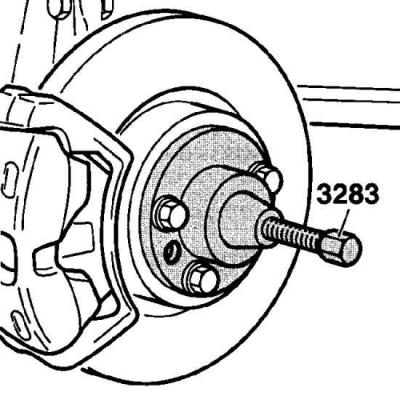
6. If the drive shaft is very tight in the hub, use the VW-3283 puller to remove it.
Cars with automatic transmission
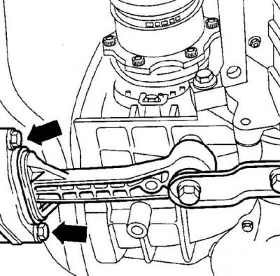
7. Unscrew the two bolts securing the powertrain pendulum support to the beam.
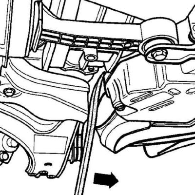
8. Insert a pry bar between the beam and the engine block and move the engine block forward, while removing the tripod joint.
Installation
1. Before installing the drive shaft, clean the splines on the drive shaft and in the wheel hub.
2. Align the splines and insert the drive shaft into the wheel hub.
3. Clean the twelve-point nut support surface and coat it with a thin layer of oil.
4. Screw in new twelve-point nuts.
5. Insert the outer joint of the drive shaft into the wheel hub until it stops.
6. Using new bolts, screw the lower front suspension joint to the wishbone and tighten the mounting bolts to 20 Nm, then turn them 90° further.
7. Bolt the drive shaft to the gearbox flange and tighten the mounting bolts to 40 Nm.
Cars with automatic transmission
8. Screw in and tighten the bolts securing the power unit pendulum support to the beam to a torque of 25 Nm.
9. Screw on the twelve-sided drive shaft mounting nut and tighten it to a torque of 300 Nm. To keep the hub from turning, an assistant should press the brake pedal.
10. Loosen the twelve-sided nut one turn.
11. Tighten the twelve-sided nut to a torque of 50 Nm, then turn it further through an angle of 30°.
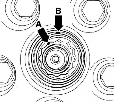
12. To turn the twelve-sided nut further by an angle of 30°, make one mark on the teeth of the nut (arrow A) and the second mark on the hub opposite the adjacent tooth (arrow B) and, turning the nut further, align the marks.
13. Install the front wheels, then lower the vehicle and tighten the wheel nuts.
14. Install the decorative wheel cover.
Visitor comments