
English Русский
Български
Беларускі
Український
Српски
Hrvatski
Română
Polski
Slovenský
Magyar
  |  Articles  |  Sitemap  |  Contacts  |    |
Car maintenance Ford Car maintenance Hyundai Car maintenance Chevrolet Car maintenance BMW Car maintenance Audi Car maintenance Opel Car maintenance AvtoVAZ
VWmanual.ru


Main   Passat   Golf   Polo   Touareg   Tiguan   Sharan   Transporter   Others  
Polo 3 (1995-2003) Polo 4 (2001-2009)

Timing belt drive with single pulley injection pump (VW Polo 3)

  • Main
  • Polo
  • Polo 3
  • Power unit
  • Diesel engines 1.7 and 1.9
  • Timing belt drive with single pulley injection pump
            0


Contents: Removal ↓ Engines AEY, ANV, AKW ↓ Engines AFN, AHU, ALE ↓ For all engines ↓ Installation ↓

Removal


1. Remove the ribbed belt.

2. Remove the ribbed belt tensioner roller, if installed.

3. Remove the upper part of the timing belt cover and the cylinder head cover.

4. Align the TDC marks of the piston of cylinder No.1 on the crankshaft: A - AEY, AHB, AKW engines, B - AFN, AHU, ALE engines (Fig. 6.3).
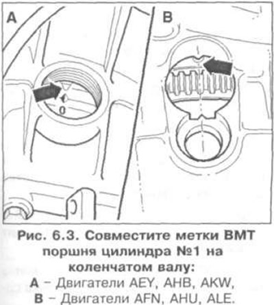
4. Align the TDC marks of the piston of cylinder No.1 on the crankshaft: A - AEY, AHB, AKW engines,…


Engines AEY, ANV, AKW


5. Install adjusting tool 2068 A as shown in Fig. 6.4. Set the adjusting tool to 5 mm (arrow A). Rotate the crankshaft so that the TDC marks on the flywheel coincide with the mark on the setting tool (arrow B).
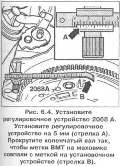
5. Install adjusting tool 2068 A as shown in Fig. 6.4. Set the adjusting tool to 5 mm (arrow A).…


Engines AFN, AHU, ALE


6. Install the 2068 A adjuster as shown in Fig. 6.5. Set the adjuster to 96.0 mm. The reference point is the graduated mark on the left side of the vernier (arrow A). Rotate the crankshaft until the TDC marks on the flywheel align with the mark on the adjuster (arrow B).
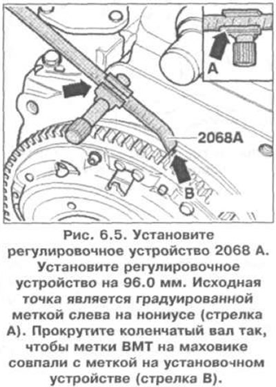


6. Install the 2068 A adjuster as shown in Fig. 6.5. Set the adjuster to 96.0 mm. The reference…


For all engines


7. Lock the camshaft pulley using the lock (Fig. 6.6).
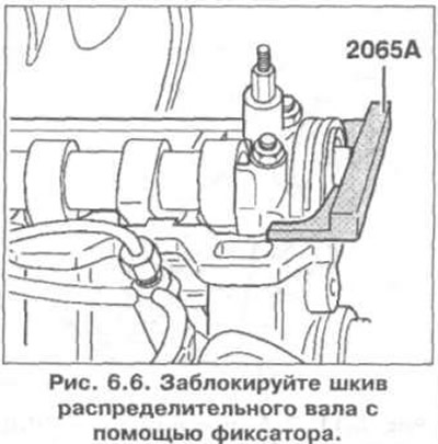
7. Lock the camshaft pulley using the lock (Fig. 6.6).


8. Lock the fuel injection pump pulley using the locking pin (Fig. 6.7).
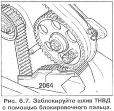
8. Lock the fuel injection pump pulley using the locking pin (Fig. 6.7).


9. Loosen the tension roller.

10. Remove the coolant pump pulley (use VAG 1590 to loosen and tighten the mounting bolt).

11. Remove the crankshaft pulley/damper.

12. Remove the lower part of the timing belt cover.


13. Mark the direction of rotation of the timing belt.

14. Remove the intermediate roller.

15. Remove the timing belt.

Installation


16. Make sure that the TDC mark on the flywheel and the reference point are aligned.

17. Loosen the camshaft pulley mounting bolt by 1/2 turn (Fig. 6.8). Disconnect the pulley from the hub using a hammer and punch.
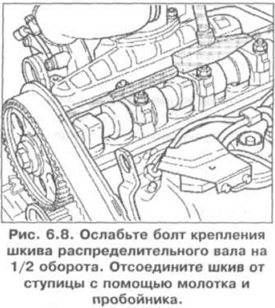
17. Loosen the camshaft pulley mounting bolt by 1/2 turn (Fig. 6.8). Disconnect the pulley from the…


18. Install the timing belt in the direction of travel and remove the fuel injection pump pulley locking pin.

19. Install the intermediate roller. Tightening torque - 25 Nm.

20. Tighten the timing belt (Fig. 6.9). Using a wrench, turn the tension roller in the direction of the arrow (clockwise) so that the marks (arrows) align.
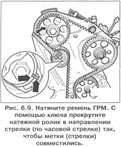
20. Tighten the timing belt (Fig. 6.9). Using a wrench, turn the tension roller in the direction of…


21. Tighten the tension roller locking nut. Tightening torque: 20 Nm.

22. Check again that the TDC mark on the flywheel and the reference point are aligned.

23. Tighten the camshaft pulley mounting bolt to 45 Nm.

24. Remove the camshaft pulley retainer.

25. Turn the crankshaft two revolutions in the direction of rotation so that the TDC marks on the crankshaft are aligned.

26. Check the alignment of the TDC marks on the flywheel, check the locking of the camshaft pulley using a locking device, check the locking of the fuel injection pump pulley, check the installation and ease of rotation of the tension roller.

27. If the marks are not aligned, pull the tension roller with a wrench, loosen the fastening nut, rotate the eccentric clockwise so that the marks are aligned, and tighten the nut to 45 Nm.

28. Turn the crankshaft two revolutions in the direction of rotation so that the TDC marks on the crankshaft are aligned.

29. Repeat the checks.

30. Install the timing belt cover parts, damper and cylinder head cover.

31. Install the ribbed belt.

32. Check the fuel injection pump supply.

The original information is posted on the resource VWManual

This article is available at russian, bulgarian, belarusian, ukrainian, serbian, croatian, romanian, polish, slovak, hungarian
The text has been checked: Kolesnikov Artem

Share information:

Previous articles
Disassembling the engine
Diesel engines AKW, ANV 1.7 SDI, AEY 1.9 SDI, AFN, AHU and ALE 1.9 TDI, 1Y 1.9 D
Next articles
Timing belt drive with double pulley injection pump
Sealing flange and flywheel / drive disc / pressure disc
Crankshaft
Connecting rod and piston group
Checking the piston protrusion at TDC
Cylinder head


Similar articles from other manuals for VW cars:
Adjusting the tension of the power steering pump drive belt Passat B2 (1981-1988)
Timing Belt (Camshaft Drive Belt) Golf 1 (1974-1984, petrol)
Checking the belt drive pulleys for misalignment (4.2L petrol… Touareg 1 (2002-2006)
Timing chain drive Tiguan 1 (2007-2015)
Installing the toothed drive belt and adjusting the timing drive Sharan 1 (1995-2000)
Tensioning and replacing the timing belt Transporter T4 (1990-2003)
Power steering pump — drive belt tensioner LT 28 (1975-1991)
Link to this page in different formats


Visitor comments


No comments yet


How much will 32 + 16 =


Polo 4 
  • General information
  • User manual
  • Maintenance
  • Power unit
  • Engine repair
  • Cooling and lubrication system
  • Control system
  • Injection system (diesel)
  • Supply system
  • Exhaust system
  • Chassis
  • Front suspension
  • Rear suspension
  • Steering
  • Wheels and tires
  • Brake system
  • Body
  • Interior
  • Exterior
  • Electrical equipment
  • Equipment and devices
  • Wiper system
  • Lighting system
  • Electrical circuits
Polo 3 
  • General information
  • User manual
  • Maintenance
  • Power unit
  • Petrol engines 1.4 and 1.6
  • Petrol engines 1.4 (V16)
  • Petrol engines 1.6 and 1.8
  • Diesel engines 1.7 and 1.9
  • Diesel engines 1.9 D and TD
  • Transmission
  • Mechanical gearbox 085
  • Mechanical gearbox 020/02K
  • Chassis
  • Front suspension
  • Rear suspension
  • Steering
  • Brake system
  • Body
  • Exterior
  • Interior
  • Electrical equipment
  • Equipment and instruments (until 2000)
  • Equipment and instruments (after 2000)
  • Electrical circuits
  • Wiring diagrams (petrol)
  • Wiring diagrams (diesel)
VWmanual.ru © 2016-2026 | Mobile version | News and articles | Sitemap: EN BG BY UA RS HR RO PL SK HU | Write message | Site search
Passat B2 • Passat B3 • Passat B4 • Passat B5 • Passat B6 • Golf 1, diesel • Golf 1, petrol • Golf 2, petrol • Golf 2 • Golf 3 • Golf 4 • Golf 5 • Polo 3 • Polo 4 • Touareg 1 • Tiguan 1 • Sharan 1 • Transporter T3 • Transporter T4 • LT 28 • LT 2D • Beetle • Caddy 3 •
Our website uses cookies to ensure functionality and convenience.