



Contents: Table 6.1 a. Piston ring clearance…↓ Table 6.2 a. Piston and cylinder…↓ Table 6.2 b. Piston and cylinder…↓
The piston and connecting rod are shown in Fig. 6.14.
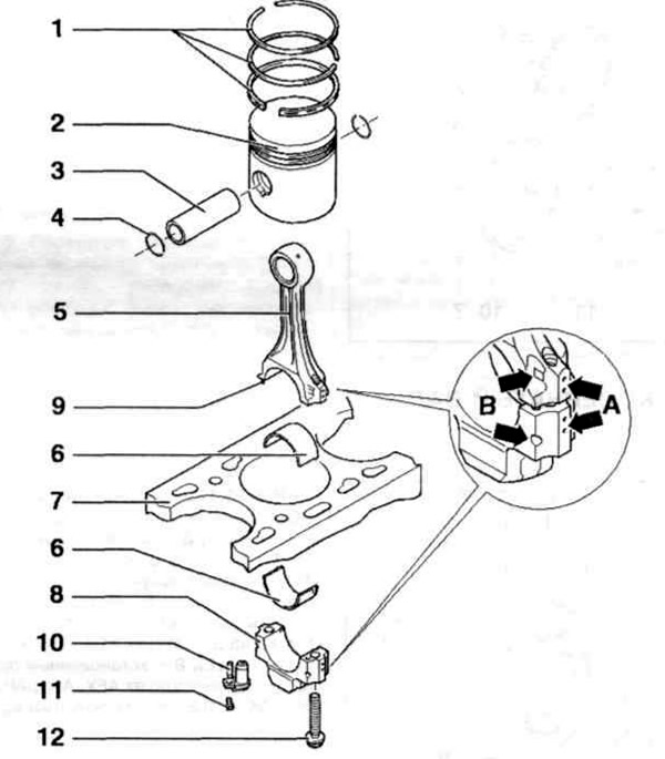
Fig. 6.14. Piston and connecting rod:
1 - Piston rings; 2 - Piston; 3 - Piston pin; 4 - Retaining ring; 5 - Connecting rod; 6 - Inserts; 7 - Cylinder block; 8 - Connecting rod cover; 9 - Mounting pin; 10 - Oil can; 11, 12 - Bolts.
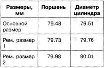
Checking the piston ring clearance is shown in Fig. 6.15. Checking the clearance between the piston ring and the piston groove is shown in Fig. 6.16. The dimensions of the piston ring clearances are given in Table 6.1a, the dimensions of the clearances between the piston ring and the piston groove are given in Table 6.16. The dimensions of the pistons are given in Tables 6.2 a, b.
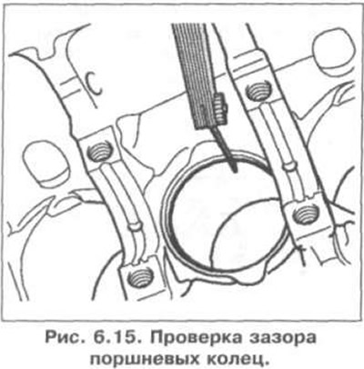
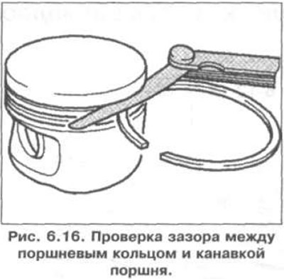
Table 6.1 a. Piston ring clearance dimensions
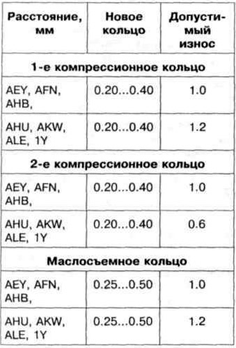
Table 6.1 b. Dimensions of gaps between piston ring and piston groove
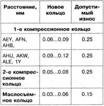
Table 6.2 a. Piston and cylinder dimensions of AEY, AFN, AHB, AHU, AKW, ALE engines
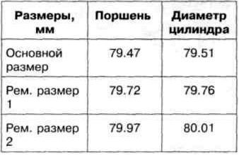
Table 6.2 b. Piston and cylinder dimensions of the 1Y engine
Visitor comments