



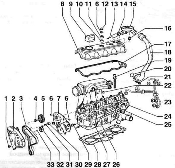
Fig. 6.19. Cylinder head:
1, 4, 6, 19, 29, 31 - Bolts; 2 - Upper part of the timing belt protective cover; 3 - Timing belt; 5 - Camshaft pulley; 7 - Rear timing belt guard; 8 - Cylinder head cover; 9 - Oil filler cap; 10 - Upper sealing washer; 11 - Washer; 12 - Lid; 13 - To the crankcase ventilation system; 14 - Clamp; 15 - Pressure regulating valve; 16 - Bushing; 17 - Cylinder head cover gasket; 18 - Crankcase ventilation tube; 20 - Sealing ring; 21 - Lower cone seal; 22, 33 - Nuts; 23 - High pressure fuel lines; 24 - Cylinder head; 25 - Injectors; 26 - Glow plugs; 27 - Lifting eye; 28 - Cylinder head gasket; 30 - Intermediate roller (only on engines AEY, AFN, AHB, AHU, AKW, ALE); 32 - Tension roller.
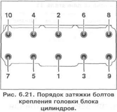
Checking the cylinder head deformation is shown in Fig. 6.20. The order of tightening the cylinder head mounting bolts is shown in Fig. 6.21. Tightening torque of the cylinder head mounting bolts: 1st stage - 40 Nm, 2nd stage - 60 Nm, 3rd stage - 90°, 4th stage - 90°.
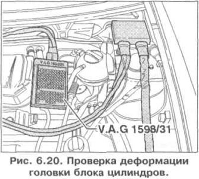
Cylinder head deformation: 0.1 mm.
Visitor comments