
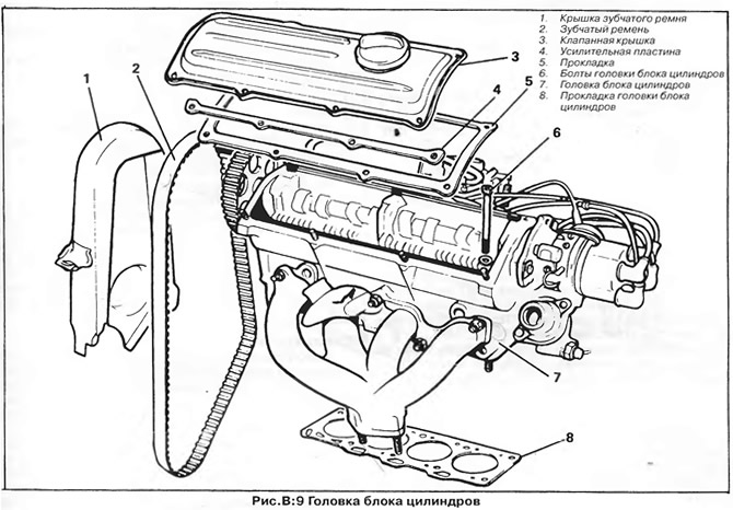
Cylinder head bolts
Two types of bolts can be used to attach the cylinder head, so when installing new parts such as the cylinder block, cylinder head and gasket, it is important to determine exactly which type of bolts are used.
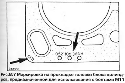
Initially, the cylinder head bolts had an M10 thread and an 8 mm hex head; from July / August 1976, they began to install M11 bolts with a head with an internal hexagon of 10 mm. The cylinder block, cylinder head and head gasket have been modified accordingly (the diameter of the hole for bolts and mounting sleeves is increased by 1 mm). The cylinder head gasket of the new sample can be distinguished by the designation "M11" in the corner of the gasket, the part number embossed on the gasket and the bolt holes larger than the old gasket (pic. AT 7).
The new cylinder heads supplied as spares are equipped with bushings that reduce the diameter of the bolt holes to 10.4 mm. If such a head is installed on a cylinder block with threaded holes for M11 bolts, the bushings must be removed.
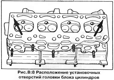
If an old head is installed on a new cylinder block, two holes must be drilled into which the mounting sleeves are inserted (shown by arrows in fig. AT 8), up to 11.5 mm, and the rest of the bolt holes (8 holes) - up to 12 mm.
In these cases, M11 bolts and a new type of cylinder head gasket should be installed (with enlarged holes).
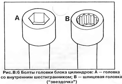
In July 1977, hexagon socket bolts were replaced with socket head bolts of the type "star" (pic. AT 6). These bolts, which have both M10 and M11 threads, are available as spare parts and can be used to replace hex bolts without changing the cylinder head. M11 bolts can be reused, but M10 slotted bolts MUST be replaced with new ones during repairs.
A special 12-point slot wrench is required to loosen and tighten new bolts ("star") size 10 mm (for M10 bolts) or 12 mm (for M11 bolts).
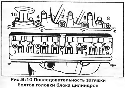
Bolts type "star" must be tightened in a strictly defined sequence (pic. AT 10), in three or four steps, respecting the required torque. Final tightening is done by turning 1/4 or 1/2 turn - depending on the size of the bolt and the year of manufacture (see section "Technical data").
Withdrawal (pic. AT 9)
I. Disconnect the negative terminal ("mass") battery.
2. Disconnect the bottom hose from the radiator and drain the coolant. The heater tap must be open. If the liquid is to be reused, collect it in a clean container.
3. Disconnect the distributor wire from the ignition coil, then the wires from the temperature sensor and carburetor (in the presence of).
4. Disconnect hoses of system of cooling from branch pipes on a head of the block of cylinders.
5. Disconnect the fuel hose and accelerator cable from the carburetor.
6 Disconnect the exhaust pipe from the exhaust manifold.
7. Remove the alternator drive belt, toothed belt cover and toothed belt as previously described.
8. Turn out two bolts of fastening of a back plate of a cover of a gear belt to a head of the block of cylinders.
9. Remove the valve cover along with the gasket. If the gasket is damaged or leaking oil, replace it.
10. Turn away bolts of fastening of a head of the block of cylinders in sequence, return shown on fig. Q:10, with a special key (see section "Cylinder head bolts").
11. Remove the cylinder head with gasket. The gasket is not reusable - install a new gasket when assembling.
Installation
Installation is carried out in the reverse order, but pay attention to the following:
1. If a new cylinder head is installed, check the interchangeability of the head, gasket and cylinder head bolts (see paragraph "Cylinder head bolts").
2 If hex head bolts have been installed, they must be replaced with type "star" (see paragraph "Cylinder head bolts").
3. M10 bolts are UNSUITABLE for reuse and must be replaced with NEW ones when installing the head. Bolts M11 "star" can be reused.
4. Be convinced that interfaced surfaces of a head and the block of cylinders are cleared of the remains of an old laying. When cleaning, be careful not to damage the surface of the aluminum head.
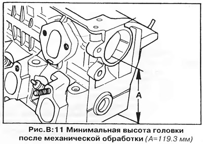
5. If the cylinder head was removed to replace a blown gasket, check the surface of the cylinder head at the gasket rupture for warping or pitting using a steel ruler and feeler gauges. If the magnitude of the irregularities (warpage) exceeds 0.1 mm, the surface should be repaired by machining or the head should be replaced. After machining, the height of the cylinder head must not be less than 119.3 mm (Ah, fig. AT 11).
6. Install a new gasket. Make sure the gasket matches the bolts and cylinder head (see paragraph "Cylinder head bolts"). The number marked on the gasket must face up (pic. AT 7). The holes in the cylinder block and gasket must match.
7. Install bolts #8 and #10 (pic. AT 8), to precisely align the head with the cylinder block. Do not tighten the bolts yet.
8. Screw in the remaining bolts and tighten them evenly in the sequence shown in fig. AT 10 O'CLOCK. Tighten the bolts in several stages, observing the required torque (see section "Technical data"). It is unacceptable to tighten the bolts in the future, after starting the engine.
9. Install the toothed belt and other parts as described earlier.
Dismantling of a head of the block of cylinders
1. Remove the intake manifold along with the carburetor and gasket. The gasket must be replaced with a new one.
2. Remove the exhaust manifold with gasket. The gasket must be replaced with a new one.
3. Remove the bolt and remove the camshaft sprocket.
4. Disconnect high-voltage wires from spark plugs and remove the distributor of ignition together with a fastening flange and a lining from a head of the block of cylinders.
5. If necessary, remove the water outlet pipe together with the thermostat.
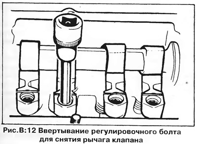
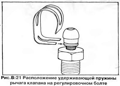
6. Remove the valve lever retaining springs from the grooves of the adjusting bolts (pic. AT 21), then screw in the bolts so that the levers sandwiched between the camshaft lobes and valves can be removed (pic. AT 12). A hex wrench is required to tighten the bolts and subsequently adjust the gaps (see section "Valve clearances" in chapter "Engine adjustment").
7. Remove the valve levers, then carefully, so as not to damage the oil seal, remove the camshaft from the head towards the ignition distributor. To protect the oil seal, wrap the camshaft shank with electrical tape.
8. Remove carbon deposits from the surfaces of the combustion chambers and valve heads with a wooden or plastic scraper. Be careful not to damage the aluminum cylinder head. Remove carbon from the pistons and cylinder block, leaving a ring of carbon around the outer edges of the pistons. Plug all holes with a rag (cooling and oil channels, etc.) and remove carbon deposits from the cylinder head and block with a jet of compressed air.
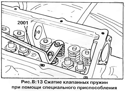
9. Using the tool, compress the valve spring and remove the two cone cotters mounted on the end of the valve stem. On fig. Figure B:13 shows the VW #2001 valve spring compression tool, which rests on the valve lever adjusting bolt. If there is no such tool, use a universal valve spring puller. Be careful not to damage the valve stem with the upper spring plate when the latter is compressed.
Remove the spring compressor and remove the upper spring cup and spring. Remove the oil seal from the valve stem (caps are unsuitable for reuse - they should be thrown away and new ones should be installed during assembly). Remove the lower spring plate. Remove the valve from the cylinder head and mark it in order to install it in its original place in the future.
10. Clear all details of a head of the block of cylinders. Remove the remnants of the old gasket from the mating surfaces.
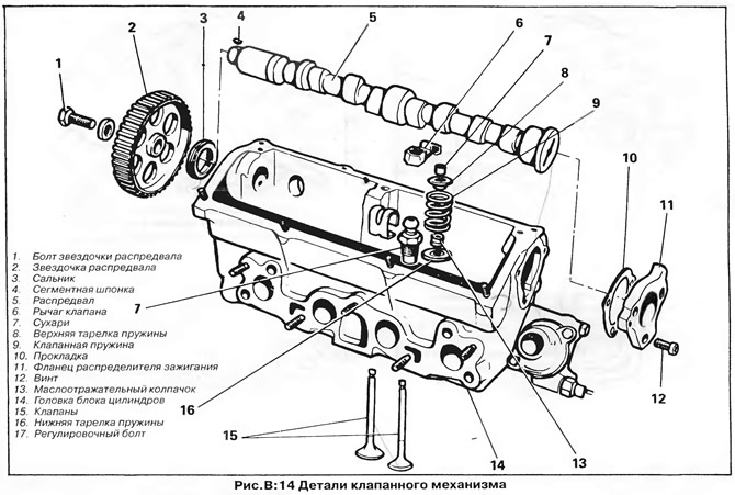
Valves - inspection and repair (pic. Q:14)
Clean the valves and inspect them for pitting, burning or other damage.
To remove carbon from the valve head, the easiest way is to clamp the valve stem into the chuck of an electric drill and, at low speed, scrape off the carbon with a file or screwdriver. Finish the valve with sandpaper.
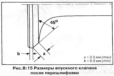
Inspect the edges and surface of the valve head for pitting, grooves, scratches, cracks, or other damage. intake valves can be restored (regrind) on a special machine for grinding valves. Do not remove more metal than necessary to eliminate surface defects. If, after grinding, the width of the edge of the valve head has decreased to 0.5 mm (pic. Q:15), the valve must be replaced, as it will overheat when the engine is running.
Machining of exhaust valves is not allowed - only manual lapping is possible.
Inspect the valve stem surface for excessive or abnormal wear. Replace valve if necessary.
Valve guides
After a significant run, oval wear appears on the end of the guide hole on the spring side in a plane perpendicular to the axis of the crankshaft. Check the guide for wear.
Check clearance between each valve stem and guide. Lift the valve head off the seat until the stem end is flush with the guide, then rock the valve from side to side. Excessive valve play in the transverse direction (more than 1.0 mm for intake and 1.3 mm for exhaust valves) indicates wear on the guide bore and/or valve stem. Repeat the test with a new valve. If the play is still excessive, the guide is worn and the cylinder head needs to be replaced.
Valve seats
Inspect the valve seat bevels for scorching or wear. Regrind the seat if necessary to restore the correct angle and bevel width. If this is not possible, replace the cylinder head (valve seats can only be replaced by a specialist company).
When regrinding seats, remove no more metal than is necessary to restore the shape of the seat. Remember that successful seat reconditioning is only possible if the valve guides are in good condition.
Simultaneously with the seats, the valves should be reground so that their mating surfaces are concentric.
Valve springs
Inspect the valve springs, their plates and crackers for wear or damage. Replace damaged parts.
Weak springs reduce engine performance, so it is recommended that a complete set of new springs be installed for any cylinder head repair. Make sure new springs are properly marked.
Camshaft and valve levers
Inspect the running surfaces of the camshaft cams and valve levers for wear or damage. Small cavities are allowed on the cam surface, which do not adversely affect the operation of the camshaft and are considered normal wear. Replacing the camshaft is not required unless the reduction in cam lift becomes excessive.
Inspect the camshaft journals for wear and damage.
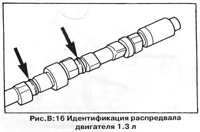
The camshafts of different engines are different; the camshaft of the 1.3 engine has cast rings between the cams of the 2nd and 3rd cylinders (pic. Q:16), and there are no marks on the 1.1 engine camshaft.
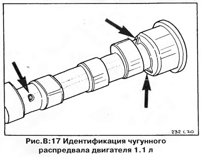
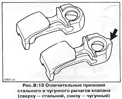
From March to July 1977, instead of steel, cast-iron camshafts, valve levers and a fuel pump pusher were installed on 1.1 liter engines. These engines are marked with the letter "N" on the timing belt cover. Cast iron and steel parts can only be replaced as a set (that is, a cast-iron camshaft must necessarily work with cast-iron valve levers, and a steel one with steel levers). The cast iron camshaft has cast corners near the neck of the 3rd bearing and is marked with the letter "D" (pic. Q:17). Cast iron valve levers can be identified by the cast lug on the side of the adjusting bolt (pic. Q:18), and the cast-iron pusher of the fuel pump is marked with the number No. 0.25V.
Cylinder Head - Assembly
Assemble the cylinder head in the reverse order of disassembly. Pay attention to the following:
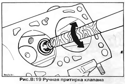
1. Valves must be lapped to their seats using first a coarse and then a fine grinding paste so as to obtain a tight fit of the valve in the seat (pic. Q:19), and a continuous dull gray ring should appear on the working chamfers of the valve and seat. After lapping, carefully remove all traces of lapping paste from the cylinder head and valves - this is very important.
2. Replace the valve stem seals, being careful not to damage them on the sharp edges of the stem.
3. When installing the valves, make sure that the conical cotters fit correctly into the groove of the valve stem and the seat of the upper spring plate.
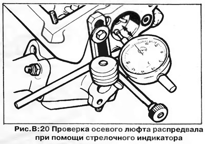
4. Insert the camshaft, then install the ignition distributor mounting flange with gasket and measure the axial play of the camshaft using a dial indicator (pic. IN 20). The axial play must not exceed 0.15 mm.
5. Install the valve levers and springs holding them. Make sure the retaining springs fit securely into the grooves of the adjusting bolts (pic. AT 21).
6. Adjust valve clearances (see chapter "Engine adjustment"), check them again after installing the cylinder head at normal engine operating temperature.
7. When installing all parts (intake and exhaust manifolds, water outlet, ignition distributor mounting flange, etc.) use new gaskets.
8. Install the cylinder head to the engine, then install the ignition distributor (see chapter "Engine electrical equipment").
Visitor comments