



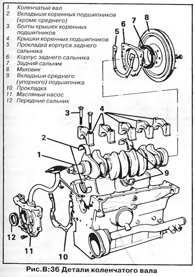
Contents: Disassembly (figure B:35 and B:36) ↓ Inspection and repair ↓ Cylinder walls ↓ Pistons ↓ Piston rings ↓ Crankshaft ↓ Main and connecting rod bearing…↓ Measuring working clearances in…↓ Assembly ↓
Disassembly (figure B:35 and B:36)
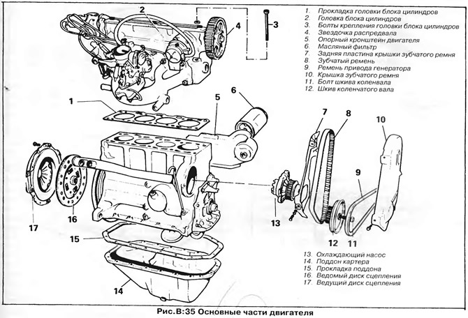
1. Loosen the alternator drive belt, remove the belt, then remove the alternator.
2. Remove the timing belt.
3. Remove the rear plate of the timing belt cover and remove the cooling pump from the cylinder block.
4. Remove the valve cover and evenly loosen the cylinder head mounting bolts in the reverse order shown in Figure B:10. Remove the cylinder head and remove the gasket.
5. Unscrew the oil filter element from the base on the cylinder block.
6. Remove the clutch from the flywheel. Secure the flywheel, unscrew its mounting bolts and remove the flywheel from the crankshaft flange.
7. Turn the cylinder block over and remove the oil pan.
8. Loosen the bolts and remove the crankshaft rear oil seal housing.
9. Remove the crankshaft pulley. Loosen the oil pump and oil intake mounting bolts and remove the oil pump.
10. For each connecting rod in turn:
- a) Bring the connecting rod to the bottom dead center (BDC) position by turning the crankshaft.
- b) If the connecting rod and cover are not marked, mark them according to the cylinder number using a center punch.
- c) Loosen the connecting rod bearing cap nuts, tap the nuts lightly to loosen the cap, then completely unscrew the nuts and remove the cap from the connecting rod.
- d) Push the piston up out of the cylinder and carefully remove it together with the connecting rod from the cylinder block.
- d) Remove the connecting rod bearings from the connecting rod and cap. Mark the bearings if they are to be reused.
11. Loosen the main bearing cap bolts evenly and remove the caps. Carefully lift the crankshaft and remove it.
12. Remove the main bearing shells from the caps and bearing beds in the crankcase. Mark the shells if they are to be reused.
13. If necessary, disassemble the piston and connecting rod assembly in the following order:
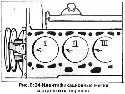
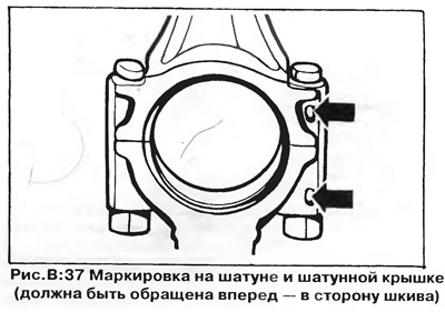
- a) Mark the piston by applying a mark on its bottom in accordance with the cylinder number (figure B:34). Mark the front side of the piston with an arrow. The marks on the connecting rod and connecting rod cap should also be placed on the front side (facing the crankshaft pulley - Figure B:37).
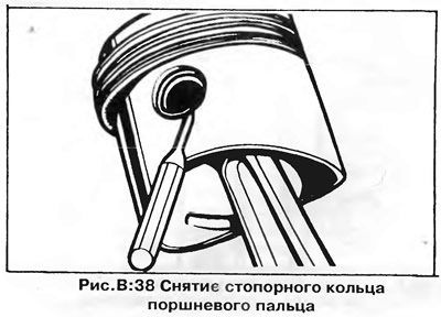
- b) Carefully press the retaining rings from both piston bosses using a sharp tool (figure B:38).
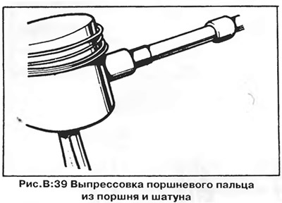
- c) Press out the piston pin using a suitable mandrel (figure B:39). If you soak the piston in hot water for a few minutes, this will make the operation easier.
- d) Remove the piston rings through the piston head.
Inspection and repair
NOTE: Inspection and repair of cylinder head components was discussed earlier in the section "Cylinder head".
Cylinder walls
Inspect the cylinder walls for scratches and roughness. Inspect the top and bottom of the cylinder for a ridge (bead) that appears as a result of wear on the rest of the cylinder.
If there are no obvious signs of cylinder wear, check the cylinder with an accurate internal micrometer. Measure the diameter of each cylinder at three different levels. First, set the micrometer parallel to the crankshaft axis, and then perpendicular to it. The difference between the two measurements at the same level will show the cylinder's ovality value, and the difference between the measurements at the top and bottom of the cylinder in the same plane will show its taper value (figure B:42).
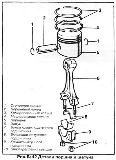
Minor surface defects can be removed by honing; cylinders with deep scratches, pitting or excessive wear should be rebored to the next (enlarged) repair size. Leave the cylinder boring operation to a specialized company that has the necessary equipment.
CAUTION: When reboring cylinders, to avoid deformation of the main bearing bore, all main bearing caps must be installed in place, therefore the cylinder block must be handed over to the plant with the bearing caps installed.
After boring, honing or deglazing, the cylinders should be washed with soapy water or detergent and wiped dry with a lint-free cloth. Then lubricate the cylinders with engine oil to prevent corrosion.
Pistons
Clean the piston surfaces from all deposits: scrape off carbon deposits, remove resinous deposits with a solvent. Do not use a caustic solution or a wire brush to clean the pistons.
Remove carbon deposits from the piston grooves. Use a special groove cleaning tool or use a piece of an old piston ring as a scraper. Be careful: if the groove side surface is damaged, excessive ring play will form, which will not create a sufficient seal, causing excessive fuel consumption. Clean the oil drain holes in the oil scraper ring grooves.
Inspect each piston for cracks, scratches, and other damage. "Spongy," eroded areas at the edge of the piston crown are usually caused by detonation or pre-ignition. Inspect the piston grooves for high steps on the inside of the lower side surfaces of the grooves. Replace pistons that show signs of abnormal wear or damage.
Piston rings
When rebuilding an engine, it is always recommended to install new piston rings. If new rings are installed in an old cylinder, first remove the gloss from the cylinder walls using a special device (honing) or fine sandpaper (in the latter case, it is necessary to carefully remove all traces of abrasive from the cylinder walls after processing).
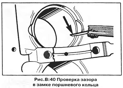
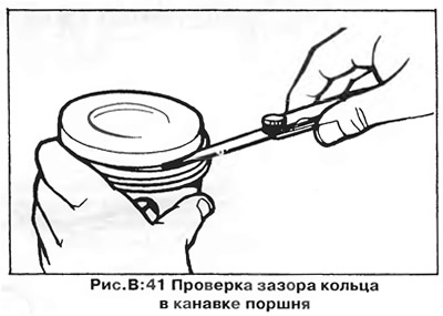
Measure the gap in the lock of each piston ring by installing the ring in the corresponding cylinder (figure B:40). To install the ring straight into the cylinder, use an upside-down piston. If the clearance is not as specified, install another set of rings. Measure the clearance of each ring in its corresponding piston groove (figure B:41). The feeler gauge should move freely around the entire circumference without jamming.
Inspect each piston, connecting rod and rings for wear or damage and replace parts as necessary.
Crankshaft
Inspect the shaft journals for scratches, nicks, grooves and other defects.
Measure the diameter of each journal in at least four places using an accurate micrometer to determine out-of-roundness, taper, or undersize. If the taper or out-of-roundness is excessive, or if the journal surface has serious defects, regrind or replace the crankshaft. If the diameter of at least one journal is not within the minimum allowable limits after machining, replace the crankshaft.
Main and connecting rod bearing shells
Clean the bearing shells thoroughly with gasoline or other similar solvent and dry them with compressed air. Do not scrape off resinous deposits from the shells.
Inspect the working surface of each insert for scratches, chips or cavities, replace defective inserts. If the gap does not exceed the permissible value with a visible steel base of the insert, there is no need to replace the insert.
If there are no visible defects, check the bearing clearances as described below.
The value of the permissible clearance in the main and connecting rod bearings is given in the section "Technical data".
Measuring working clearances in bearings
Checking the clearance in the main and connecting rod bearings is carried out using a special device of the type "Plastigauge".
NOTE: "Plastigauge" — trade name for a precisely calibrated plastic measuring strip manufactured by Plastigauge Mfg. Co., Hewarts Lane, Bognor Regis, Sussex, P021 3DR.
1. Clean the surfaces of the crankshaft, bearing shells and caps from oil and dirt.
2. Install the upper halves of the liners into their corresponding beds in the crankcase, inserting the liner locks into the bed recesses. The liners installed in the crankcase have a lubrication groove, unlike the flat cover liners.
3. Carefully lower the crankshaft onto the bearings.
4. Install the lower half of the liner into the bearing cap being measured, making sure it is installed correctly.
5. Place a piece of strip "Plastigauge" on the crankshaft journal along the axis, shifting it from the center by approximately 6 mm.
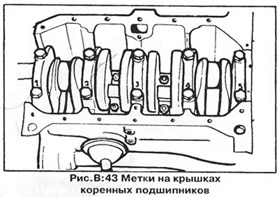
6. Install the main bearing cap and tighten the bolts to the specified torque (see section "Technical data"). Remember that bearing caps are not interchangeable, each cap has a number and must be installed only in its place (figure B:43). Take measurements for each bearing separately - there is no need to install the caps of the remaining bearings.
7. Remove the bolts and the bearing cap. Remember that the crankshaft must be stationary during the inspection.
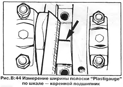
8 Measure the width of the flattened plastic strip using the scale on the packaging "Plastigauge" (figure B:44). The widest point shows the minimum clearance value, the narrowest point shows the maximum clearance value. The difference between the two measurements gives the value of the neck taper.
9. Clean the journal and bearing shell from traces "Plastigauge". Rotate the crankshaft a quarter turn and repeat the measurement. The difference between the two measurements will give the journal out-of-roundness value.
10. Thoroughly clean the crankshaft journal and bearing from traces "Plastigauge" - This is very important.
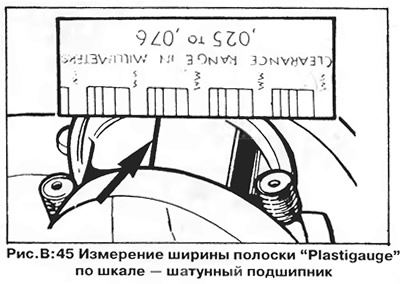
11. Connecting rod bearing clearances are measured in the same way as main bearing clearances (figure B:45).
Assembly
1. Install dry liners in the beds and caps of the main bearings. Note that the liners of the middle main bearing have thrust surfaces, since this bearing is thrust and limits the axial movement of the crankshaft. Make sure that the locks of the liners enter the corresponding recesses in the crankcase.
2. Lubricate the working surfaces of the bearings and the crankshaft journal with engine oil and carefully lower the crankshaft onto the bearings.
3. Install the main bearing caps in their corresponding places, determined by the markings on the caps (remember that the caps cannot be interchanged - Figure B:43). Tighten the cap bolts with a torque of 6.5 kg·m. Check the ease of rotation of the crankshaft.
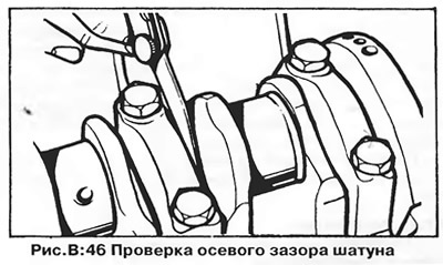
4. Measure the crankshaft axial play Move the shaft forward as far as it will go to remove the axial play in one direction, and measure the clearance between the center main bearing thrust surface and the crankshaft web using feeler gauges (figure B:46). The gap should be within 0.07-0.18 mm, the maximum allowable gap is 0.20 mm.
5. Assemble the pistons with the connecting rods as follows: Heat the piston to 60° in hot water, then lubricate the piston pin holes in the connecting rod and the piston bosses with graphite grease. Assemble the connecting rod with the piston so that the arrow on the piston head and the marking on the connecting rod and cap are on the same side (figure B:34 and B:37). Press the piston pin into the piston and secure it on both sides with retaining rings. Make sure the retaining rings are seated correctly in the grooves.
6. Install the rings on the pistons according to the instructions that come with the new rings. Install the rings from the bottom of the piston, starting with the bottom (oil scraper). The lower compression and oil scraper rings have a "TOP" mark on one of their surfaces, which should be facing upwards. In repair kits of rings intended for installation in old (not bored) cylinders, the top ring usually has a stepped groove along the outer edge, designed to prevent the ring from contacting the ridge (bead) formed at the top of the cylinder due to wear. This ring should be installed with the stepped part upward.
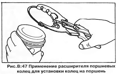
When installing rings on the piston, use a special expander to expand them (figure B:47) - this eliminates the possibility of ring breakage or piston damage.
7. For each connecting rod with piston in turn:
- a) Make sure the piston and connecting rod markings match and are correctly oriented.
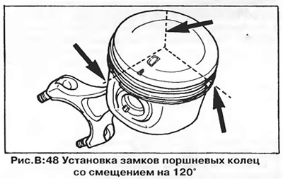
- b) Install the piston rings so that their locks are offset from each other by 120° (figure B:48).
- c) Generously lubricate the cylinder walls and piston rings with clean engine oil.
- d) Insert the piston with the connecting rod into the corresponding cylinder, orienting it correctly (the arrow on the piston bottom should point towards the crankshaft pulley - Figure B:34).
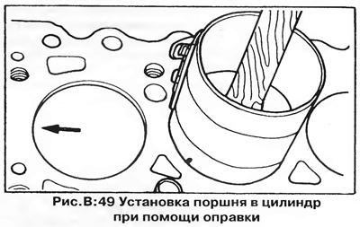
- d) Compress the rings using a special mandrel (figure B:49). Push the piston out of the mandrel and into the cylinder using the wooden handle of a hammer until the bottom of the piston is just below the top edge of the cylinder (figure B.49). Be careful not to hit the crankshaft with the connecting rod. Do not attempt to install the pistons by hand (without a frame) - this may lead to breakage of the rings.
- e) Install new bearing shells (dry) into the cap and the small head of the connecting rod so that the bearing lock fits into the corresponding recess in the connecting rod.
- g) Lubricate the crankshaft journal and connecting rod bearing shells with clean engine oil, then tighten the connecting rod firmly to the journal and install the cap on the connecting rod.
- h) Make sure that the markings on the connecting rod and cover match; during assembly, they should be on the same side.
- i) Secure the connecting rod cap with new nuts. Before installation, lubricate the nuts and tighten them to a torque of 3.0 kg·m, then tighten by turning another 90°.
- k) Check the axial clearance of the connecting rod on the crankpin using feeler gauges (figure B:53). The connecting rod clearance should be within 0.05-0.31 mm.
8. Assemble the remaining parts in the reverse order of their removal.
Visitor comments