
Removal - All Engines
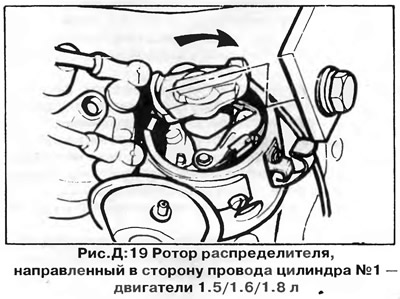
1. Disconnect the wire "masses" from the battery, turn the crankshaft so as to bring the piston of cylinder No. 1 to TDC of the end of the compression stroke (see chapter "Engine adjustment"), then remove the distributor cap. The rotor should be directed towards the contact of the spark plug wire of the 1st cylinder.
2. Disconnect the condenser wires and vacuum tube. On vehicles with electronic ignition, disconnect the stabilizer connector (module) idle and transistor block.
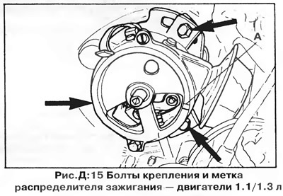
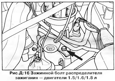
3. Turn away bolts of fastening of the distributor of ignition - three bolts on the engine 1.1/1.3 l (pic. D:15) or one clamp bolt on 1.5/1.6/1.8L engines (pic. D:16). Carefully remove the distributor from the engine, remembering the position of the rotor - if necessary, make a mark on the housing before removal.
WARNING: It may be necessary to rotate the housing to remove the distributor.
Installation - 1.1/1.3 engines
1. Make sure the No. 1 cylinder piston is at TDC at the end of the compression stroke.
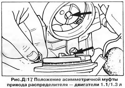
2. Mark the position of the asymmetric distributor drive clutch in the cylinder head and rotate the distributor shaft so that the slot of the clutch is aligned with the projections on the distributor shaft during installation (pic. D:17).
3. Insert the distributor, aligning its shaft with the asymmetric drive coupling.
4. After installation, the rotor should point to the contact of the spark plug wire of cylinder No. 1 on the cover, as well as to the mark on the distributor body (Ah, fig. D:15).
5. Fix the distributor in this position, replace the distributor cap and connect the capacitor and wires.
6. Connect the battery, start the engine and adjust the ignition timing with the strobe lamp (see chapter "Engine adjustment").
7. Completely tighten bolts of fastening of the distributor and attach a vacuum tube.
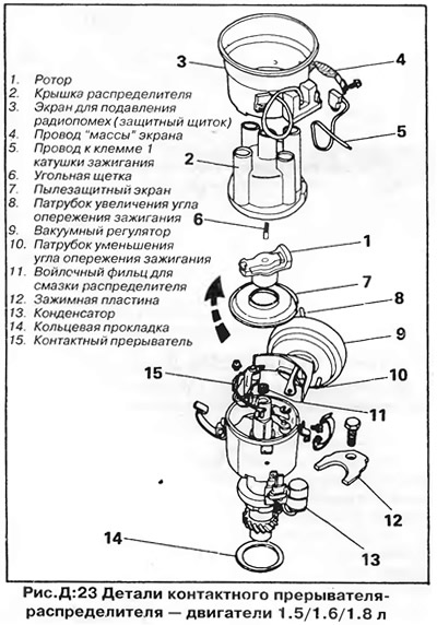
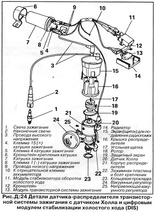
Installation - engines 1.5 / 1.6 / 1.8 l
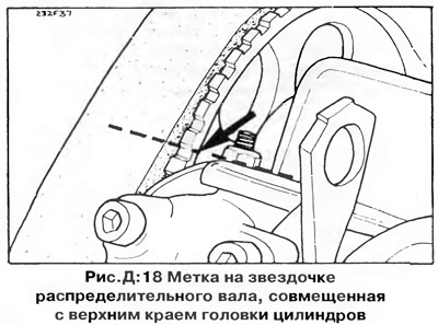
If the position of the crankshaft has changed, the alignment marks must be aligned before installing the distributor. Remove the TDC sensor or plastic plug from the hole in the top of the clutch housing. Rotate the crankshaft until the TDC mark ("0") on the flywheel or drive plate will not line up with the pointer in the hole. The mark on the camshaft sprocket should at the same time be at the level of the upper edge of the cylinder head, as shown in fig. D:18. If not, turn the crankshaft one full turn and check the alignment again. With aligned marks, the piston of cylinder No. 1 is set to the TDC position of the end of the compression stroke.
On early models, there is no mark on the camshaft sprocket. Remove the valve cover and rotate the engine so that the lugs on both cylinder #1 cams on the camshaft are facing up.
Install the oil pump drive shaft so that the slot on the end of the shaft is parallel to the axis of the crankshaft.
Make sure the gasket (sealing washer) on the distributor flange in good condition and correctly positioned. Install the distributor rotor so that it aligns with the mark on the housing made when the distributor was removed, then install the distributor by inserting the protrusion on the end of the distributor shaft into the slot in the oil pump drive shaft. When installed, the rotor should rotate slightly and align with the groove on the edge of the distributor housing (pic. D:19). If alignment does not occur, remove the distributor and install it again, after slightly turning the rotor.
Fix the distributor with a clamping plate and a bolt. Connect the vacuum hose and the high and low voltage wires. On contactless ignition distributors, connect the connector of the wires coming from the control unit, then set the ignition timing, as described in chapter "Engine adjustment". Finally tighten the clamping plate bolt.
Repair
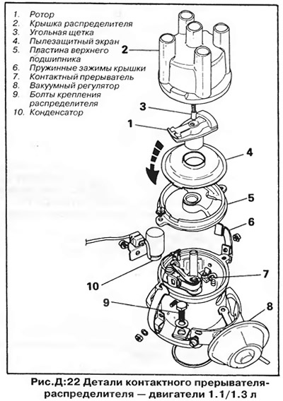
All early model engines have a conventional Bosch breaker-distributor (except for some 1.1L engines with Ducellier distributor). Later models of 1.5, 1.6 and 1.8 liter engines are equipped with an electronic ignition system with a Hall sensor.
In most cases of wear or damage to distributor parts (shaft, weights of the centrifugal ignition timing controller), especially after a high mileage of the car, it is most economical to replace the distributor assembly.
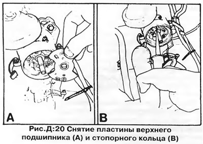
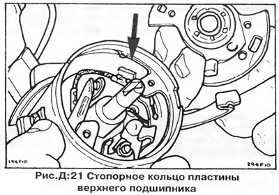
The only easily replaceable part of the distributor is the upper bearing plate, located on the top of the distributor and fixed with two screws to the distributor body or to a plate held in the body by a retaining ring (pic. D:20 and D:21). The upper bearing plate must be removed to replace the breaker contacts - see chapter "Engine adjustment".
The rest of the distributor is a non-separable unit, and in case of wear, the distributor should be replaced with a new one.
Visitor comments