
English Русский
Български
Беларускі
Український
Српски
Hrvatski
Română
Polski
Slovenský
Magyar
  |  Articles  |  Sitemap  |  Contacts  |    |
Car maintenance Ford Car maintenance Hyundai Car maintenance Chevrolet Car maintenance BMW Car maintenance Audi Car maintenance Opel Car maintenance AvtoVAZ
VWmanual.ru


Main   Passat   Golf   Polo   Touareg   Tiguan   Sharan   Transporter   Others  
Golf 1 (1974-1984, diesel) Golf 1 (1974-1984, petrol) Golf 2 (1984-1993, petrol) Golf 2 (1984-1993) Golf 3 (1991-1997) Golf 4 (1997-2004) Golf 5 (2003-2008)

Checking the charging circuit (VW Golf 1)

  • Main
  • Golf
  • Golf 1
  • Power unit
  • Engine electrical equipment
  • Checking the charging circuit
            0


Contents: Security measures ↓ Verification procedure ↓

Security measures


When performing any work on electrical circuits associated with a generator, it is important to follow these rules:

1. Never disconnect or rearrange the battery cables while the generator is running, otherwise the rectifier and/or voltage regulator may be damaged. It is not advisable to make any connection or disconnection in the charging circuit while the engine is running.

2. Never allow the generator to rotate with the power cable disconnected if the excitation windings are under voltage from the battery; otherwise the rectifier diodes may be damaged.

3. When connecting wires to the battery, always carefully observe the polarity of their connection - if connected incorrectly, the semiconductor devices of the car will be damaged (in particular, rectifier diodes). It is recommended to connect the positive (+) cable to the positive (+) battery terminal first, then the negative (-) cable to the negative (-) terminal.

4. Always disconnect the battery ground before connecting the charger to isolate the alternator from the battery and external charging equipment. The charger should be connected to the battery in parallel (positive battery terminal to the positive terminal of the charger, negative to the negative).

Verification procedure


1. Make sure that the alternator drive belt is tensioned correctly (see chapter "Car maintenance work"). The battery must be in good condition, its terminals, as well as other connections and wires of the charging circuit must be clean, securely tightened and provide good contact.


2. Check the vehicle's electrical system for leakage current, which can discharge the battery while the vehicle is parked and make charging difficult. Disconnect the positive cable from the battery and connect an ammeter between the cable and the positive terminal of the battery. With all electrical devices disconnected, (clocks, interior lighting, headlights, etc.) the ammeter should show a current of no more than 10 mA. If the current is large, find out and eliminate the cause.

3. Disconnect the wire connectors from the rear of the alternator, then connect the negative terminal of the voltmeter to ground and turn on the ignition. Connect the other terminal of the voltmeter to each of the disconnected wires of the alternator in turn. If there is no voltage on the blue wire coming from the indicator lamp on the instrument panel, check the discharge indicator lamp circuit and the lamp itself.

4. If there is no voltage on the main (red color) charging circuit power wires going to the starter, check the wires and electrical connections between the battery, starter and generator.

5. If no fault is found, check the generator output current under load as follows:

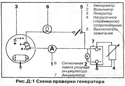
Disconnect the connectors and install a jumper between the blue wire and its terminal on the generator. Connect an ammeter between the power (red) wires and their contacts on the generator. Connect a voltmeter to the battery terminals. Connect a resistor between the positive battery terminal and the "ground" that provides a load current of 30 A in the circuit (figure D:1). With the engine speed at 3000 rpm, headlights, heater fan and rear window defroster on, the generator output current should correspond to that specified in section "Technical data".

Disconnect the connectors and install a jumper between the blue wire and its terminal on the…


To ensure the required generator power, the voltage between the battery terminals should not fall below 13 V. If the voltage is low, check the voltage regulator in the following order:

6. With the engine speed at 3000 rpm in the circuit assembled according to the diagram in Figure D:1, adjust the load resistance so that the generator output current is 25 A (generator 35 A), 30 A (generator 45 A), 35 A (generator 55 A) or 45 A (generator 65A). If the voltage regulator is working properly, the voltmeter reading should be between 12.5 V and 14.5 V. If the regulator does not provide the specified voltage, replace it.

7. Check the voltage drop in the positive branch of the charging circuit as follows:
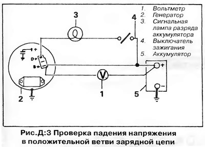
  • Assemble the test circuit as shown in Figure D:3. Run the engine at 3000 rpm and turn on the headlights. If the voltmeter reading is greater than 0.5 V, the positive branch of the charging circuit is faulty.
  • If the positive branch of the charging circuit is OK, check the voltage drop on the negative branch.
If the positive branch of the charging circuit is OK, check the voltage drop on the negative branch.


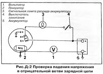
Assemble the circuit shown in Figure D:2. If the voltmeter readings exceed 0.25 V, the negative branch of the charging circuit is faulty - check the connections of the battery and the power unit to the "ground".
Assemble the circuit shown in Figure D:2. If the voltmeter readings exceed 0.25 V, the negative…


NOTE: Most problems with the battery charging system are caused by worn alternator brushes or a faulty voltage regulator.


The procedures for replacing the brushes and voltage regulator are described in this chapter. It is recommended that more complex faults be repaired by an auto electrician. It may be more economical to install a new generator assembly than to purchase individual parts and repair the generator.

CAUTION: To avoid damage to semiconductor devices, ALWAYS disconnect the battery before starting any work on the electrical system.

This article is available at russian, bulgarian, belarusian, ukrainian, serbian, croatian, romanian, polish, slovak, hungarian
The text has been checked: Tarasov Ivan

Share information:

Previous articles
Tools and equipment
General information about the engine electrical equipment
Next articles
Removal and installation the generator
Generator repair
Ignition distributor
Ignition coil
Checking the starter
Removal and installation the starter


Similar articles from other manuals for VW cars:
Checking hydraulic tappets Passat B3 (1988-1993)
Removal and installation the generator/checking the generator… Polo 4 (2001-2009)
Checking the battery open circuit voltage Touareg 1 (2002-2006)
Checking the operation of the intake manifold flap Tiguan 1 (2007-2015)
Checking the engine oil level and replacing it Sharan 1 (1995-2000)
Windshield Washer Water Pump — Checking and Replacing Transporter T4 (1990-2003)
Checking the electrolyte level in the battery Caddy 3 (2003-2010)
Link to this page in different formats


Visitor comments


No comments yet


How much will 48 + 22 =


Golf 5 
  • General information
  • User manual
  • Maintenance
  • Troubleshooting
  • Power unit
  • Engine repair
  • Cooling and ventilation system
  • Fuel system
  • Ignition system
  • Transmission
  • Clutch
  • Mechanical gearbox
  • Automatic gearbox
  • Chassis
  • Brake system
  • Car suspension
  • Steering
  • Body
  • Interior (internal elements)
  • Exterior (external elements)
  • Doors and covers
  • Electrical equipment
  • Power devices
  • Washers and wipers
  • Lighting and appliances
  • Electrical circuits
Golf 4 
  • General information
  • User manual
  • Weekly checks
  • Maintenance
  • Power unit
  • Petrol engines
  • Diesel engines
  • Cooling system
  • Fuel system (petrol)
  • Control system (petrol)
  • Fuel system (diesel)
  • Exhaust system
  • Transmission
  • Clutch
  • Car gearbox
  • Drive shafts
  • Chassis
  • Car suspension
  • Steering
  • Wheels and tires
  • Brake system
  • Body
  • Exterior (external elements)
  • Interior (internal elements)
  • Ventilation and heating
  • Car doors and sunroof
  • Washers and glass cleaners
  • Electrical equipment
  • Power devices
  • Lighting and appliances
  • Electrical circuits
Golf 3 
  • Petrol engine
  • Engine repair
  • Lubrication system
  • Cooling system
  • Ignition system
  • Diesel engine
  • Engine repair
  • Diesel injection system
  • Pre-glow system
  • Transmission
  • Clutch
  • Gearbox and drive shafts
  • Chassis
  • Steering
  • Wheels and suspension
  • Brake system
  • Electrical equipment
  • Lighting and appliances
  • Electrical circuits
Golf 2 
  • General information
  • Introduction to guide
  • User manual
  • Petrol engines 1.3 l
  • Engine repair
  • Lubrication system
  • Cooling system
  • Carburetors
  • Supply system
  • Ignition system
  • Petrol engines 1.6/1.8 l
  • Engine repair
  • Supply system
  • Ignition system
  • Diesel engines
  • Engine repair
  • Lubrication system
  • Cooling system
  • Power and exhaust system
  • Transmission
  • Clutch
  • 4-speed gearbox 084
  • 5-speed gearbox 085
  • 4-speed gearbox 020/4R
  • 5-speed gearbox 020/4T
  • Automatic gearbox
  • Drive shafts
  • Chassis
  • Steering
  • Car suspension
  • Brake system
  • Body
  • Body elements
  • Doors, locks and windows
  • Electrical equipment
  • Equipment and devices
  • Power devices
Golf 2 (petrol) 
  • General information
  • Characteristics
  • Car care
  • Maintenance
  • Power unit
  • Engine repair
  • Engine 1.05/1.30
  • Engine 1.60/1.80
  • Cooling and lubrication system
  • Power and exhaust system
  • Transmission
  • Clutch
  • Car gearbox
  • Drive shafts
  • Chassis
  • Brake system
  • Steering
  • Suspension
  • Body
  • Body and equipment
  • Electrical equipment
  • Lighting and appliances
  • Electrical circuits
Golf 1 (petrol) 
  • General information
  • Characteristics
  • User manual
  • Maintenance
  • Power unit
  • Engine adjustment
  • Engine 1.1/1.3
  • Engine 1.5/1.6/1.8
  • Engine electrical equipment
  • Cooling system
  • Fuel system
  • Transmission
  • Clutch and manual gearbox
  • Automatic gearbox
  • Chassis
  • Steering
  • Front suspension
  • Rear suspension
  • Brake system
  • Electrical equipment
  • Lighting and appliances
  • Electrical circuits
  • Body
  • Body and equipment
  • Optional equipment
Golf 1 (diesel) 
  • General information
  • Specifications
  • Maintenance
  • Power unit
  • Engine repair
  • Exhaust and turbocharger
  • Cooling system
  • Fuel system
  • Fuel injection system
  • Transmission
  • Clutch and drive shafts
  • Car gearbox
  • Chassis
  • Suspension and wheels
  • Steering
  • Brake system
  • Wheels and tires
  • Body
  • Heating and ventilation
  • Exterior (external elements)
  • Interior (internal elements)
  • Doors and windows
  • Electrical equipment
  • Equipment and devices
  • Lighting system
  • Power devices
  • Electrical circuits
VWmanual.ru © 2016-2026 | Mobile version | News and articles | Sitemap: EN BG BY UA RS HR RO PL SK HU | Write message | Site search
Passat B2 • Passat B3 • Passat B4 • Passat B5 • Passat B6 • Golf 1, diesel • Golf 1, petrol • Golf 2, petrol • Golf 2 • Golf 3 • Golf 4 • Golf 5 • Polo 3 • Polo 4 • Touareg 1 • Tiguan 1 • Sharan 1 • Transporter T3 • Transporter T4 • LT 28 • LT 2D • Beetle • Caddy 3 •
Our website uses cookies to ensure functionality and convenience.