



Contents: Inspection of breaker contacts…↓ Checking the gap of the breaker…↓ Adjusting the breaker contacts…↓ Replacing breaker contacts (figure…↓ Capacitor ↓ Checking the centrifugal ignition…↓ Vacuum regulator ↓ Distributor cap, rotor, high-tension…↓ Lubrication of the ignition…↓ Setting the ignition timing ↓
The Golf, Jetta and Scirocco models can be equipped with either a conventional ignition system with a contact breaker-distributor or a contactless electronic ignition system operating on the "Hall effect" principle. There are two types of contact breaker-distributors, one of which is designed for 1.1/1.3 l engines, and the other for 1.5/1.6 l engines. A contactless distributor with a Hall sensor, working together with an electronic module, is installed on late 11/1.3 l engines and on 1.6/1.8 l engines (see chapter "Engine electrical equipment"). All distributors are manufactured by Bosch.
Distributors for 1.1/1.3 l engines of different years of production may differ slightly - the main difference is in the method of fastening the upper bearing plate
NOTE: The operations described below regarding the breaker contacts and the capacitor apply only to contact breaker distributors. The remaining operations apply to all types of distributors.
Access to the breaker contacts is opened after removing the metal protective shield (if installed), distributor cap, rotor and plastic protective screen (if available), and also (on 1.1/1.3 l engines) upper bearing plates of the distributor shaft. All types of distributors have a screen to suppress radio interference - before removing it, you will need to disconnect the short "ground" wire. The bearing plate is secured with two screws, the distributor cap - with two spring clips, and the rotor is tightly mounted on the shaft.
NOTE: On late 1.1/1.3L engine distributors, the upper bearing plate is secured with a retaining ring rather than screws. To remove the plate, remove the retaining ring using retaining ring pliers.
Inspection of breaker contacts (figure B:6 and B:7)
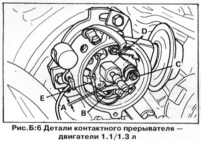
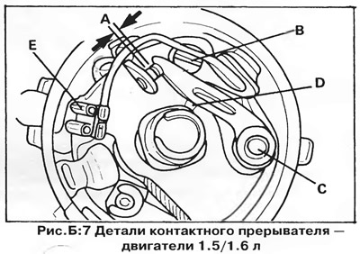
Use a screwdriver to spread the contacts and inspect them. If the contacts are burnt or deformed by erosion (a "peak" has formed on one of them, and a "crater" on the other), then it is recommended to replace them with new ones. As a last resort, it is permissible to clean the contacts (file off the "peak" with a thin file or sandpaper), and then adjust the gap between them, as described below.
If the contacts turn blue due to overheating, this indicates a possible capacitor malfunction. The capacitor should be replaced at the same time as the contacts.
Checking the gap of the breaker contacts
The gap between the breaker contacts can be measured either directly (A, figure B:6 and B:7) using a flat probe, or by measuring the angle of the closed state of contacts (UCC). Measuring the UCC, as a rule, does not require removing the cover and rotor of the distributor and gives more accurate results, since the measurement result does not depend on the shape of the contacts (i.e., on the presence of a "crater" and "peak" on them). Relatively inexpensive devices for measuring the UCC are available for sale; in addition, many digital tachometers can function as a UZOK meter.
NOTE: On the 1.1/1.3L engine distributor, the upper distributor bearing plate must be in place when measuring the contact gap, otherwise incorrect clearance values will be obtained due to the large radial offset of the shaft. There is a cutout in the plate for inspection and adjustment of the contacts.
Measure the gap using a feeler gauge in the following order:
Remove the distributor cap and rotor. Turn the engine in the direction of normal rotation so that the movable contact shoe is positioned on one of the cam apexes of the distributor shaft and the contacts are separated to the maximum distance. Insert a feeler gauge of the appropriate thickness between the contacts (see section "Technical data"). If the gap is correct, the feeler gauge should fit tightly between the contacts, but move easily, leaving the contacts stationary. If necessary, adjust the contacts as described below.
NOTE: If a "peak" has formed on one of the contacts due to spark erosion, the probe should be inserted between the edges of the contacts to obtain a correct result. In this case, it is better to measure the UZOK.
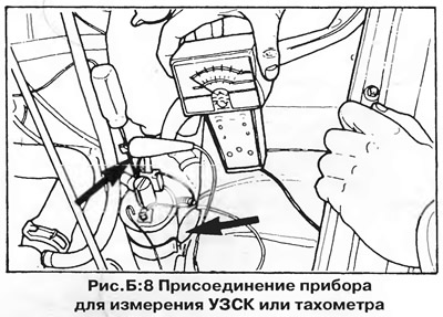
To measure the UZSK using a special device, you do not need to remove the distributor cap. Connect the red (+) wire of the UZSK meter to the negative ("-" or "No. 1") terminal of the ignition coil connected to the distributor, and the black (-) wire to the "ground" of the car (for example, to the ignition coil bracket) — see Figure B:8. Start the engine in idle mode and make sure that the instrument readings correspond to the UZSK value specified in Section "Technical data".
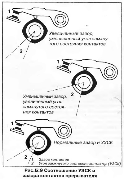
Remember that the larger the gap between the breaker contacts, the smaller the UZSK, and vice versa (figure B:9).
To check the general condition of the distributor, perform another UZSK measurement at an engine speed of 2000 rpm. If the result differs from the previous one by more than 3° in either direction, then the distributor shaft bushings are heavily worn, or the cam apexes are unevenly worn.
Adjusting the breaker contacts (figure B:10 and B:11)
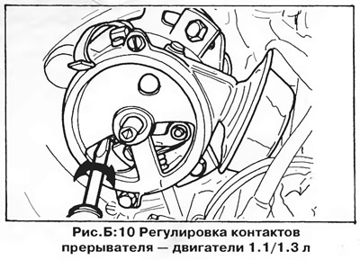
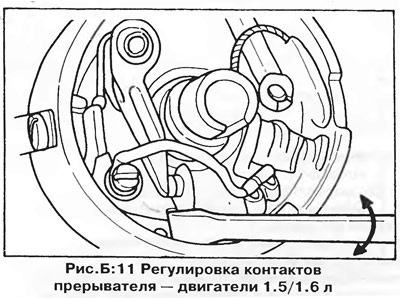
When installing new contacts, adjust the initial gap using a flat feeler gauge. It is recommended to set the maximum permissible gap value (or the minimum permissible value of the UZSK), since due to wear of the moving contact pad the gap decreases over time (UZSK - increases).
If the gap (UZSK) does not correspond to that specified in the section "Technical data", adjust the contacts in the following order:
1. Turn the crankshaft in the direction of normal rotation so that the movable contact shoe is positioned on one of the tops of the distributor shaft cam and the contacts are separated to the maximum distance.
2. Loosen the locking screw of the fixed contact of the breaker (B, Figure B:6 and B:7).
Using a screwdriver inserted into the adjustment slot (figure B:10 and B:11), move the fixed contact, increasing or decreasing the gap. If the gap is correct, the feeler gauge should fit tightly between the contacts, but move easily, leaving the contacts stationary. Tighten the locking screw and measure the gap between the contacts again.
4. Measure the breaker contact gap at each cam lobe. If the gap values vary greatly due to uneven cam wear, the distributor or cam should be replaced.
5. If possible, check the value of the UZSK and, if necessary, repeat the adjustment. If the UZSK is too large, the gap between the contacts should be increased; if the UZSK is small, the gap should be decreased.
6. After adjusting the contacts, check and adjust the initial ignition timing.
Replacing breaker contacts (figure B:6 and B:7)
1. Disconnect the connector from the junction block on the wall of the distributor (E, Figure B:6 and B:7).
2. Loosen the screw securing the contacts and remove the contacts together with the screw.
3. Wipe the new contacts with methyl alcohol to remove any remaining grease. Before installing the contacts, apply a very thin layer of universal grease to the movable contact shaft and the surface of the distributor shaft cam. Apply two or three drops of liquid oil to the felt pad at the end of the distributor shaft. Check/adjust the gap between the breaker contacts.
After lubricating, make sure that no oil or grease gets on the working surfaces of the contacts. If necessary, wipe the contacts with gasoline or methyl alcohol.
Capacitor
If the contacts of the breaker are heavily damaged by erosion, burnt or discolored, this indicates a possible capacitor malfunction. The result of such a malfunction may be a decrease in spark energy on the spark plugs, which may result in interruptions in operation and loss of engine power.
The best way to check a capacitor is to replace it with a known good one.
The capacitor is located on the outside of the distributor housing. To remove the capacitor, disconnect its wire from the insulated junction block and unscrew the mounting screw.
Checking the centrifugal ignition timing regulator
Check the operation of the centrifugal regulator using a stroboscope, directing the beam of its lamp to the installation mark of the crankshaft pulley with the engine running (figure B:13).
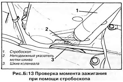
When the throttle valve is gradually opened, the mark on the crankshaft pulley should smoothly move away from the fixed pointer in the direction opposite to the direction of rotation of the pulley. When the throttle valve is closed, the mark should return to its original place. If the pulley mark moves jerkily, this indicates that the regulator weights are jammed. If the mark fluctuates, then it is possible to assume that the regulator springs are weakened or broken, as well as significant wear of the distributor shaft bearings.
To inspect the centrifugal governor, remove the plate with the breaker contacts. In many cases, cleaning and lubricating the springs, weights, and other parts is enough to restore normal operation of the governor.
Vacuum regulator
To check the vacuum regulator, the easiest way is to disconnect the vacuum tube from the carburetor and apply a vacuum to it, sucking air with your mouth and simultaneously observing the vacuum regulator rod, which should move, turning the plate at a certain angle (the distributor cap must be removed). When the vacuum is suddenly released, the breaker plate should click back into its original position.
If the plate returns to its original position slowly, then it is possible that the mechanism is contaminated or the return spring is broken. If the regulator does not work when a vacuum is applied, then the diaphragm may be damaged.
NOTE: Some distributors are equipped with a double-acting vacuum regulator, which can not only increase but also decrease the ignition timing angle - for this purpose it has two vacuum chambers on either side of the diaphragm. In this case, the operation of the regulator should be checked in both directions, first applying vacuum to one branch pipe and then to the other.
Distributor cap, rotor, high-tension wires and ignition coil
Wipe the distributor cap inside and out with a clean cloth, paying particular attention to the space between the metal contacts (figure B:12). Make sure the contacts are not damaged by erosion. Make sure there are no traces of sparking on the surface of the cover, which look like thin black zigzag lines caused by sparking between the contacts of the high-voltage wires. Such traces usually cannot be removed, so the damaged cover should be discarded and replaced with a new one. Check the condition of the carbon brush in the center of the distributor cap.
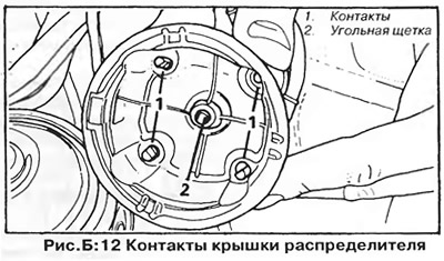
Clean the rotor and inspect it carefully for any damage or excessive contact erosion. Make sure the rotor is tightly seated on the distributor shaft.
Clean the ignition coil cover and inspect it carefully for damage and signs of sparking.
Clean the high-voltage wires from dirt and grease and check the integrity of their insulation. Make sure the wires have good contact with the coil, distributor and spark plugs. Check the integrity of the protective caps.
Lubrication of the ignition distributor
Electronic ignition system distributors do not require lubrication during maintenance, however, contact type breaker distributors must be lubricated at each inspection and contact adjustment.
1. Lubricate the camshaft surface with a thin layer of universal grease (D, Figure B:6 and B:7).
2. Lubricate the centrifugal regulator mechanism. It is convenient to use a special oil in an aerosol can with a flexible nozzle. The nozzle should be inserted into the distributor through the cutouts in the upper bearing plate and the breaker plate. Make sure that the oil does not get on the breaker contacts.
Setting the ignition timing
On engines with a contact breaker, set the initial ignition timing after servicing (cleaning, checking or replacement) contacts of the breaker and adjustment of the UZSK. In addition, the ignition timing should be adjusted in all cases where the distributor has moved from its place, regardless of the type of ignition system. It is important that the gap between the contacts (UZSK) is correctly adjusted before setting the ignition timing.
The original material is available on the portal vwmanual.ru
The most accurate way to set the ignition timing is with a stroboscope, although an approximate setting can be made without it - see chapter "Engine electrical equipment".
Warm up the engine, disconnect the vacuum regulator hose, then connect the strobe and tachometer to the ignition system. There are many different designs of these devices, differing in power sources and connection methods, so they should be connected in accordance with the manufacturers' instructions.
The operating principle of the stroboscope is as follows: the sensitive element of the stroboscope is connected to the spark plug wire of cylinder No.1 (figure B:13), and at the moment the current passes through the wire (therefore, at the moment of spark formation in the cylinder) sends a pulse, which causes a short flash of the stroboscope lamp. If the light of the lamp is directed at the crankshaft pulley, it will illuminate it only at the moments of flashes in cylinder No.1, and the pulley mark will always be in the same place relative to the stationary pointer. Since the flashes occur more than ten times per second, the observer's eye sees the pulley only at the moment when it is illuminated, so it seems that 4, the mark on the pulley is stationary. The visible position of the mark relative to the pointer shows the actual ignition advance angle at that moment.
If the mark is poorly visible, it should be highlighted with white paint before testing. In the figure B:14 and B:15 (engines 1.1/1.3) two versions of the timing marks and indicators corresponding to 10° and 5° before TDC respectively are shown. On 1.5/1.6/1.8 engines (figure B:16) the installation mark is applied to the flywheel and is visible through a special hole closed with a threaded plug. Figure B:16 shows the alignment of the marks in the TDC position and 7.5/9° before TDC.
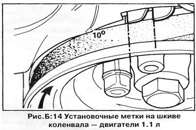
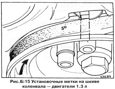
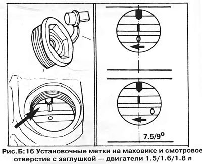
Remember that as the engine speed increases, the ignition timing angle changes due to the operation of the centrifugal regulator, therefore, when adjusting the initial ignition timing, it is necessary to maintain the value specified in the section "Technical data" engine speed. In addition, the vacuum regulator tube should be disconnected and plugged.
If the instrument panel does not have a tachometer, use a portable tachometer to measure engine speed. Connect the tachometer to the low voltage ignition circuit as follows:
Connect the positive (red) tachometer wire to the negative ("-" or "No. 1") terminal of the ignition coil, and the negative (black) wire to the vehicle's ground. If the ignition coil terminals are covered by a plastic connector housing, insert a piece of wire or a thin screwdriver into the connector and connect the tachometer wire to it (figure B:8).
Start the engine and set the idle speed. Aim the strobe light at the crankshaft pulley timing mark and the pointer (figure B:13). The mark must occupy a stable position in relation to the pointer.
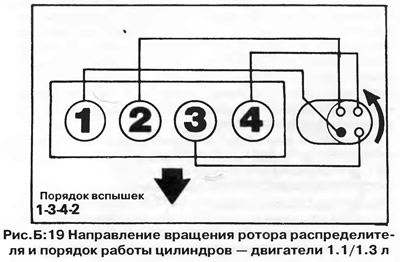
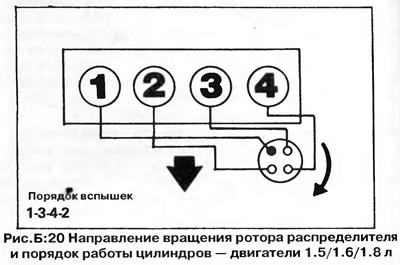
When the ignition is set correctly, the mark should be aligned with the pointer - see section "Technical data". If the marks do not match, loosen the distributor mounting bolts (figure B:17 or B:18) and carefully rotate its housing until the marks are aligned. The direction of rotation of the rotor and the order of operation of the cylinders are shown in Figures B:19 and B:20. To increase the ignition advance angle, the distributor should be turned against the direction of rotation of the rotor, and to decrease it, in the direction of rotation.
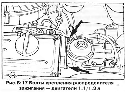
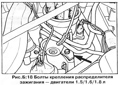
After completing the adjustment, carefully tighten the bolts and check the ignition timing again. Check the operation of the centrifugal governor by increasing the engine speed. Do not forget to reinstall the vacuum regulator hose.
Visitor comments