
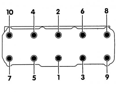
Cylinder Head Bolt Tightening Order
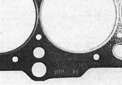
Cylinder block gasket marks
Removal and installation of a head of the block of cylinders is made on the cold engine. The exhaust manifold is not removable. The cylinder head can be removed and installed without removing the engine.
Features of removing and installing the cylinder head of a diesel engine are given in subsection 2.6.1.2.
A defective cylinder head gasket can be identified by the following signs:
- power loss;
- coolant leak. White puffs of exhaust gas when the engine is warm;
- oil leak;
- coolant in engine oil. The oil level does not decrease, but increases. Gray color of engine oil, foam bubbles on the oil level indicator, liquid oil;
- engine oil in the coolant;
- the coolant boils strongly;
- no compression in two adjacent cylinders.
Removing
1. Disconnect wire "masses" (-) from the battery.
2. Disconnect the wires from the cylinder head:
- CO potentiometer plug;
- throttle potentiometer plug;
- multi-contact connection;
- idle speed stabilization valve plug;
- cold start valve plug;
- plug-in connection for the lambda probe under the machine, on the attachment bracket on the right;
- pressure sensor plug on the power steering housing, if equipped;
- oil pressure sensor plug on the left end side of the cylinder head;
- ground wire from the cylinder head cover and intake manifold.
3. Remove the engine harness through the intake manifold, having previously marked the position of the cable clamps with a felt-tip pen. Open cable clamps or cut.
4. Remove all wires from spark plugs.
5. Remove the throttle control cable from the throttle and stop.
6. Remove the air hose at the connection between the air filter and the throttle body, unscrew and remove the idle air stabilization valve together with the bracket, remove the crankcase ventilation hose, remove the idle air stabilization hose from the air filter housing and remove the air hose together with the idle air stabilization valves.
7. Remove vacuum hoses:
- on the intake air heating throttle valve, activated carbon tank solenoid valve, Digifant control unit;
- on the brake booster check valve.
8. Remove the fuel supply line (black), starting a cold engine and fuel distributor, after loosening the clamps. Before removing, place a rag to collect escaping fuel. Seal the pipes immediately with suitable plugs. To do this, insert, for example, clean screws of a suitable diameter into the hoses.
9. Remove the fuel return line from the fuel distributor (blue), after loosening the clamp.
10. Unscrew the alternator support from the cylinder head.
11. Drain coolant (see subsection 2.16.3).
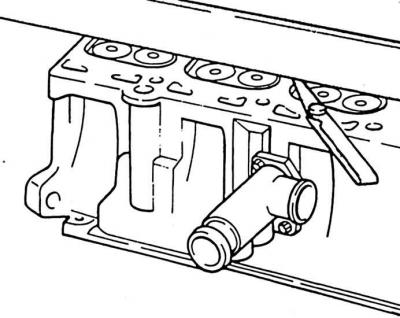
12. Unscrew the coolant fittings on the cylinder head and, without removing the hoses, set aside.
13. Unscrew exhaust pipe from exhaust manifold and cylinder head.
14. Remove the intake air heater hose from the exhaust manifold housing.
15. Unscrew the exhaust manifold cover.
16. Unscrew intake manifold.
17. Place the machine on stands.
18. Remove the engine compartment splash guard (see subsection 2.4).
19. Unscrew the exhaust pipe from the exhaust manifold. Lower the exhaust system slightly and hang it on a wire (see subsection 2.19.1).
20. Remove upper toothed belt cover.
21. Loosen the toothed belt and remove it from the top of the camshaft (see subsection 2.5.1.1).
22. Remove camshaft gear (see subsection 2.7).
23. Unscrew toothed belt tensioner.
24. Unscrew the screws securing the rear toothed belt cover.
25. Unscrew the cylinder head cover. Take out the oil separator.
26. Remove the cylinder head cover seals.
27. Loosen the cylinder head bolts with a socket wrench, e.g (HAZET990Slg-12).
Attention! Bolts must be loosened in reverse order from 10 to 1 (see fig. Cylinder Head Bolt Tightening Order). The cylinder head must be sufficiently cold before removal (room temperature), otherwise the removed cylinder head may be twisted.
28. Check that all pipes and hoses leading to the cylinder head have been removed.
29. Remove the cylinder head and install on two wooden beams. Press the rear toothed belt cover slightly before removing.
30. Remove the cylinder head gasket.
Installation
1. Before installing, clean the mating surfaces of the cylinder head and cylinder block from gasket residues with a suitable scraper. Make sure that dirt does not get into the bores of the cylinder block. Cover holes with rags.
2. Check that there is no oil in the holes for the cylinder head screws, remove if necessary. To do this, insert a clean rag into the holes and collect the oil.
Attention! If oil remains in the holes, the cylinder block may be damaged when the bolts are tightened.
3. Check the cylinder head for flatness with a steel ruler. Non-flatness is checked with a steel ruler and a petal probe over the entire surface of the cylinder head. Irregularities should not exceed 0.1 mm.
Attention! If the sealing surfaces of the cylinder head are reworked, the minimum allowable height dimension must not be lowered (see subsection 2.10.3).
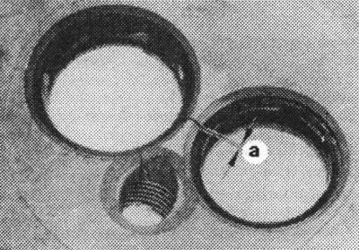
4. Cylinder heads with gaps between the valve seats and valve seat rings, as well as the first threads under the spark plug thread, can be further operated without a reduction in service life and bulkheads, if the gaps do not exceed the maximum allowable value a = max 0.5 mm.
5. Always replace the cylinder head gasket.
6. Signature "oben" should point to the cylinder head. Fit the cylinder head gasket without sealant so that none of the holes are blocked.
7. Turn the crankshaft at the belt pulley so that all pistons are approximately at the same height.
8. Install the cylinder head, while paying attention to the guide pins of the cylinder block. If necessary, install new guide pins in both external holes on the inlet side. Pay attention to the fact that the camshaft is in the TDC position for 1 cylinder (see subsection 2.5.2.1).
9. Install all 10 cylinder head bolts with washers and hand-tighten. Always replace cylinder head bolts.
Attention! Tighten the cylinder head bolts with great care. Before tightening the bolts, the accuracy of the torque wrench must be checked. The cylinder head bolts are tightened on a cold engine.
10. The cylinder head bolts are tightened with a torque wrench in sequence from 1 to 10 in two steps: first with a force of 40 Nm, and then with 60 Nm. After that, an additional tightening with a hard wrench is performed: 1/2 turn (180°). Additional tightening 90°х2 is allowed (twice at 90°each).
11. By tightening the cylinder head bolts, the angle of rotation can be estimated. Install the key handle along the engine and turn the key in one motion to the position of the handle across the engine (1/4 turn, 90°). Turn the key further - to the position of the handle again along the engine.
Attention! Tightening the cylinder head bolts on a warm engine is not permitted as part of a service or after a repair.
Attention! When replacing a cylinder head with a camshaft installed, after installing the cylinder head, lubricate the contact surfaces between the poppet followers and the cam surface with oil.
12. Set crankshaft to TDC for cylinder 1.
13. Screw on the rear toothed belt guard.
14. Screw on the camshaft sprocket and toothed belt tensioner.
15. Install toothed belt.
16. Install cylinder head cover with oil separator and new seals and tighten to 10 Nm.
17. Install the upper toothed belt cover.
18. Screw the alternator support to the cylinder head.
19. Tension the V-belt (see subsection 2.12.1).
20. Install exhaust pipe to exhaust manifold (see subsection 2.19.1).
21. Install the engine compartment splash guard.
22. Take the car off the stands.
23. Screw the exhaust pipe to the exhaust manifold and cylinder head.
24. Screw on the exhaust manifold cover.
25. Push the intake air heating hose onto the casing.
26. Install the air hose between the air filter and the throttle body together with the idle control valve.
27. Hook the throttle control cable to the throttle valve and to the stop.
28. Route the engine wiring harness through the intake manifold.
29. Connect wiring:
- CO potentiometer plug;
- throttle potentiometer plug;
- multi-contact connection of injection valves;
- idle speed stabilization valve plug;
- cold start valve plug;
- plug-in connection for the lambda probe under the machine, on the attachment bracket on the right;
- power steering pressure sensor plug, if equipped;
- oil pressure sensor plug on the left end side of the cylinder head;
- the wire "masses" from the cylinder head cover to the intake manifold.
Attention! Fasten the electrical wires in their original places with new cable clamps.
30. Put on spark plug wires.
31. Put on the vacuum hoses:
- on the intake air heating throttle valve, activated carbon tank solenoid valve, Digifant control unit;
- on the brake booster check valve.
32. Put on the fuel supply line (black) on the cold start and fuel distribution valve, fasten with clamps.
33. Put on the fuel return line (blue) on the fuel distributor and secure with a clamp.
34. Screw the coolant connection with hoses to the cylinder head.
35. Fill with coolant. Always replace the coolant.
36. Connect wire "masses" (-) to the battery. Enter the anti-theft code, program the radio stations and set the time on the clock.
Attention! Connect the battery only when the ignition is off, otherwise the fuel injection system control unit will fail.
37. Check engine oil level. If the cylinder head gasket was defective, replace the engine oil and filter.
38. Warm up the engine to operating temperature. Check again the coolant level and connections for leaks.
39. Check ignition timing (see subsection 2.14.6).
40. Check idle speed and CO content (see subsection 2.18.1).
41. Check compression pressure (see subsection 2.11).
Visitor comments