
6 cylinder engine
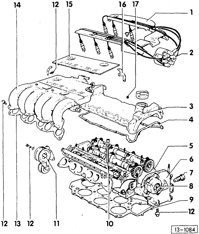
- 1 - high voltage wire guide
- 2 - ignition distributor cover with high voltage wires
- 3 - cylinder head cover
- 4 — a sealing lining of a cover of a head of cylinders
When replacing, pay attention to the installation position.
- 5 - cylinder head
- 6 — a cover of sprockets of camshafts
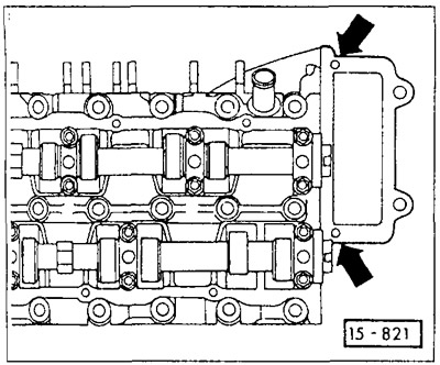
Seal the sealing surfaces with VW AMV sealant 18800102. If only the camshaft sprocket cover has been removed, prepare the cylinder head gasket for installation before installation, see Figure 15-821.
- 7 - double-row roller chain tensioner, 30 Nm
- 8 - ignition distributor
- 9 — a sealing lining of a head of cylinders
Pay attention to installation position: inscription «TOR» (top) must face the cylinder head,
- 10 — a bolt of a head of cylinders
- 11 - tension roller V-belt
- 12 - bolt, 25 Nm
- 13 — a sealing lining of the top part of an inlet collector
- 14 - the upper part of the intake manifold
First screw to the bottom of the intake manifold and then to the rear supports.
- 15 - decorative cover
- 16 - intake manifold support
- 17 - nut, 10 Nm
Removing
In principle, the cylinder head of a 6-cylinder engine is removed in the same way as the head of a 4-cylinder engine. The following indicates only significant differences in the performance of work.
Disconnect ground wire (-) battery.
Attention: this erases the engine fault codes or the radio code from the memory device. The battery can only be disconnected when the ignition is off, otherwise the injection system control unit fails. After switching off the ignition, wait at least 20 seconds to allow the thermal element of the hot air mass sensor to cool down. Before disconnecting, you must also read the instructions in the section «Removal and installation of radio», and «Removing and installing the battery».
Set the piston of cylinder 1 to the TDC position. To do this, turn the crankshaft until the tooth with the mark is against the alignment mark (from 11/91 tooth tip triangular (drawing), up to 10/91 - the top of the tooth is rounded). Vehicles with automatic transmission have 3 TDC marks on the torque converter. To find the correct TDC position, you need to remove the spark plug from cylinder 1 and use a welding electrode to check if the piston of cylinder 1 is at TDC.
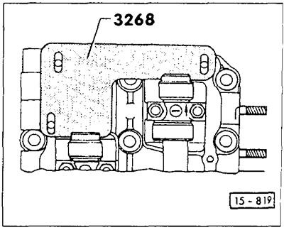
Insert the adjusting ruler VW-3268 into the grooves of both camshafts. The ruler can only be inserted when the piston of cylinder 1 is in one of the two possible TDC positions.
Before removing the drive chain, mark with paint the direction of its movement when the engine is running. If this chain is to be installed again, be sure to keep the same direction of movement.
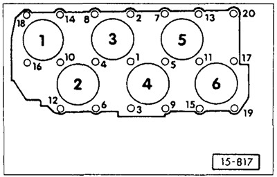
Loosen the 20 cylinder head bolts in the reverse order of their tightening, see Figure 15-817.
Installation
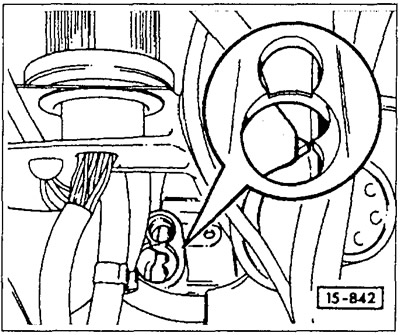
Check if the piston of cylinder 1 is at TDC. When properly adjusted, a groove should be visible on the intermediate shaft sprocket (arrow). If the groove is not visible, turn the crankshaft in the direction of rotation.
Caution: If the crankshaft turns with the cylinder head removed, have an assistant guide the double roller chain by hand so that it cannot be caught.
Check whether there are guide bushings in bores 12 and 20, insert bushings if necessary.
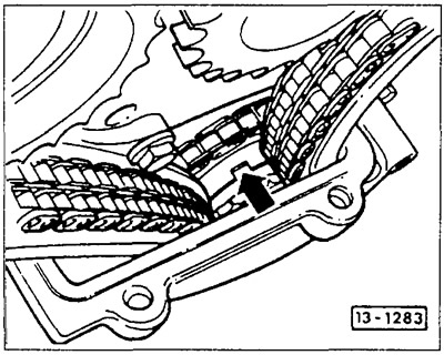
Prepare the cylinder head gasket. For this hole in the gasket with a diameter of 3 mm (arrows) clean from the old sealing mass, and then fill with VW AMV1 BB00102 sealant.
Install the cylinder head gasket so that the inscription «TOR» (top) facing the cylinder head.
Install cylinder head with shim inserted.
Insert 20 cylinder head bolts with washers and hand-tighten. The cylinder head bolts must be replaced.
The cylinder head bolts are tightened in 4 steps. In each step, tighten the bolts in sequence from 1 to 20.
- Reception 1: using a torque wrench with a torque of 40 Nm.
- Reception 2: using a torque wrench with a torque of 60 Nm.
- Reception 3: without interrupting the tightening, tighten in the direction of tightening 1/4 turn (90°) with a locked key.
- Reception 4: without interrupting tightening, tighten in the direction of tightening 1/4 turn (90°) with a locked key.
When tightening the cylinder head bolts, evaluate the key angle. Place the wrench handle along the cylinder head and turn it in one move to a position perpendicular to the axis of the head (1/4 turn is 90°).
Caution: Tightening the cylinder head bolts when the engine is warm, as part of service or repair, is not permitted.
Attention: When installing another cylinder head with a mounted camshaft instead of the old head, lubricate the contact surfaces of the poppet tappets and cams after installing the cylinder head.
Put the damper bar on the axle and screw it to the cylinder head.
Place the double roller chain on the intermediate shaft sprocket, making sure that it runs in the correct direction.
Screw on the short camshaft above cylinders 2, 4, 6 the sprocket with the installed double roller chain and clutch for the ignition distributor.
Screw sprocket with double roller chain fitted to camshaft above cylinders 1,3,5.
Remove the camshaft adjuster.
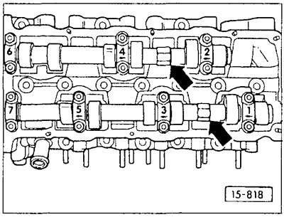
Tighten camshaft sprockets to 100 Nm. When doing this, hold the camshafts with a SW 24 key on the hexagon (arrow).
Attention: When tightening or loosening the sprockets, the camshaft adjuster must be removed.
Apply sealant AMV 18800102 to the sealing surfaces of the camshaft cover and install the cover.
Screw on the chain tensioner.
Rotate the crankshaft twice by 360°in the direction of rotation and set the piston of cylinder 1 again to TDC.
Attention: Turn the motor shaft only when the chain tensioner is installed! Otherwise, the drive chain may come off.
Check the new coolant for antifreeze content and increase the concentration if necessary, see chapter «Cooling system».
Caution: Do not reuse used coolant.
Valve timing adjustment
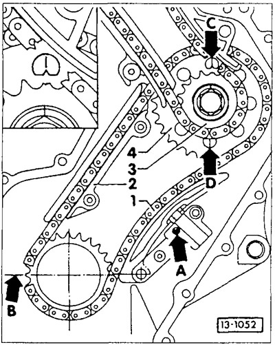
Check and, if necessary, adjust the position of the crankshaft in relation to the intermediate shaft. The ground tooth of the crankshaft sprocket -B- must be in the plane of the main bearings.
The mark on the intermediate shaft sprocket -4- must point towards the notch -C- or -D- on the shim. Arrow -A- indicates the position of the mounting hole through which the locking splines of the chain tensioner are disengaged with a small screwdriver.
Visitor comments