



Since some connections must be released on the underbody side, four stands are needed, as well as a garage jack to raise the car. Before installation work in the engine compartment, cover the fenders with covers. The hood does not need to be removed before removing the engine.
Depending on the year of manufacture and equipment of the vehicle, electrical wires, as well as vacuum and coolant hoses, may be located in the engine compartment in different ways. Since it is impossible to dwell on each option individually, it is recommended that the corresponding wire be marked with a tag before removal.
Electrical plugs are usually fixed with metal clips. Before detaching, depress the clips or compress the side lugs.
Removing
Disconnect ground wire (-) battery.
Remove battery, see chapter «Electrical system».
Remove the intake air hose from the air filter housing. Loosen hose clamps first.
Drain the coolant into a suitable container. To do this, remove the hoses from the coolant pump, see chapter «Cooling system».
Raise the car, see section «Vehicle lifting»
Unbolt exhaust pipe from exhaust manifold and transmission bracket. Lower the exhaust system a little and hang it up with a wire, see chapter «Exhaust system».
Vehicles with power steering
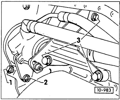
Loosen bolts -1 - and -2- of the tensioner, remove the V-belt.
Unscrew the bolts -3- of the hydraulic pump bracket and, without disconnecting the pipelines, put the hydraulic pump aside or hang it to the body on a wire. Do not remove the pump bracket from the engine.
Attention: If the hydraulic hoses are disconnected, the system must be bled after installation, see chapter «Steering».
Vehicles with air conditioning
Loosen and remove the compressor and alternator drive V-belt, see later in this chapter.
Unscrew the air conditioning compressor from the bracket and hang it on the side of the body with the pipes connected.
Caution: The coolant circulation system must not be opened. Coolant pipes are sensitive to bending, move the condenser carefully.
Disconnect the electrical wires from the main and fog lights, as well as from the turn signal lights.
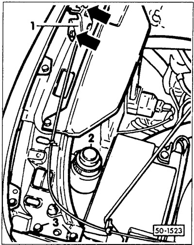
Loosen the hood latch bolts -1- (arrows), remove the Bowden cable and hood latch.
Vehicles with power steering: Release clamp from power steering fluid reservoir -2-.
Remove the front baffle. To do this, unscrew bolts -3- on both sides.
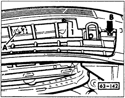
Remove ventilation grille. To do this, unscrew the cross-head screws on the left and right. Locking tabs -A- (on the back side) and -B- with a screwdriver. Tilt the ventilation grill down.
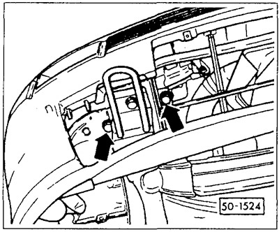
Unscrew the fastening bolts on both sides under the bumper (arrows).
Diesel engine with gas turbine supercharging
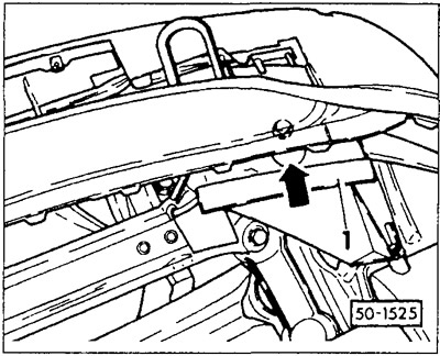
Remove the U-shaped cover -1- from the air duct of the charge air cooler and unscrew the outer bolt through the mounting hole (arrow).
Partition with headlight, slightly lift and carefully pull forward.
Caution: do not damage the front edge of the wing.
Remove the coolant hoses from the cylinder head, coolant pump and expansion tank. At the same time, use the clamp for the water pump to squeeze the clamps by the projections and loosen them.
Attention: If the coolant hoses are fixed with compression clamps, cut the clamps with side cutters and use clamps with a tightening screw during installation.
Remove the complete heatsink with fan bracket, electric fan and airflow guides.
Carbureted engine
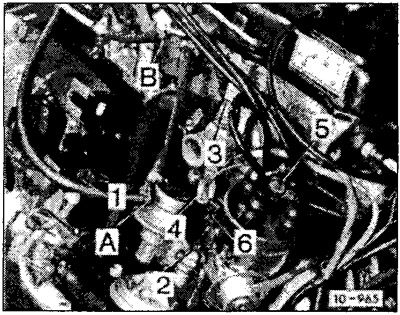
Remove the following wires or disconnect plug connectors (see photo). Release the wires at the attachment points and put them on the body.
Attention: To simplify the subsequent connection, the wires should be marked with color tags and inscribed before disconnection.
- 1 - generator
- 2 - 1.8 bar hydraulic switch
- 3 - intake manifold heater thermal switch
- 4 - starter cover thermal switch
- 5 - ignition wire (terminal 4)
- 6 - ignition distributor (terminal 1)
Remove fuel lines -A- and -B- and close openings with suitable plugs.
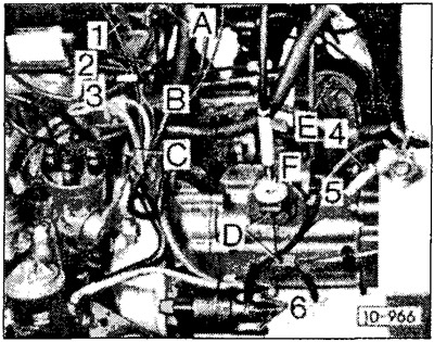
Disconnect electrical wires:
- 2 - temperature indicator sensor
- 3 - hydraulic switch 0.3 bar
- 4 - transmission ground wire
- 5 - plug from the gearbox housing 6-starter
Disconnect all wires and vacuum hoses from the carburetor.
Remove the gas draft from the carburetor and counter-support, see chapter «Supply system».
Injection engine
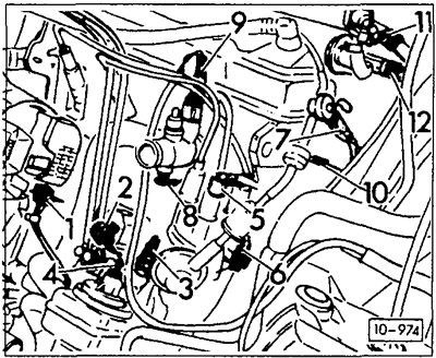
Remove or disconnect the following electrical wires:
- 1 - generator
- 2 - engine idling warm-up regulator
- 3 - 1.8 bar hydraulic switch
- 4 - engine oil temperature sensor
- 5 - ignition wire (terminal 4 from the ignition distributor)
- 6 - ignition distributor (terminal 1)
- 8 - coolant temperature sensor
- 10 - 0.3 bar hydraulic switch
Detach the earth wire from the cylinder head cover and the wiring harness from the gearbox retaining bracket.
Disconnect electrical wires from starter.
Remove throttle link, see chapter «Petrol injection system».
Diesel engine
Unscrew the fuel supply and return lines from the high pressure fuel pump.
Disconnect the electrical wires from the fuel switch and glow plugs.
All engines
Unscrew the speedometer drive shaft from the gearbox, close the hole with a cap.
Depending on the version of the gearbox, remove the clutch cable or unscrew the clutch slave cylinder from the gearbox and put it aside with the cables connected, see chapter «Clutch».
Disconnect the ground wire from the gearbox.
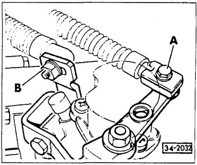
Unscrew cable ties -A- and -B- of gear selector drive and cable tie rods on gearbox.
Unscrew cardan shafts from the gearbox and hang them on the body with wire hooks, see chapter «Front axle».
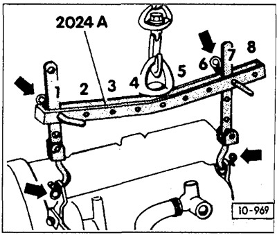
The lifting device VAG-2024A should be properly inserted into the lifting eyes of the engine (arrows), Belt pulley side: second bar hole in position 1; flywheel side: third tire hole in position 7; secure fingers with safety earrings.
Attention: In order to adjust to the center of gravity of the machine, the lifting hook rails must be properly installed in the indicated positions. Described positions 1-4 of the lifting beam are located on the side of the belt pulley. The holes in the tires are measured from the hook.
Raise the engine with a crane so as to unload its supports.
If a suspension device is not available, a suitable chain can be inserted into the lifting eyes of the engine, a suitable pipe can be inserted through it, the engine slightly raised and the pipe supported on the trestle.
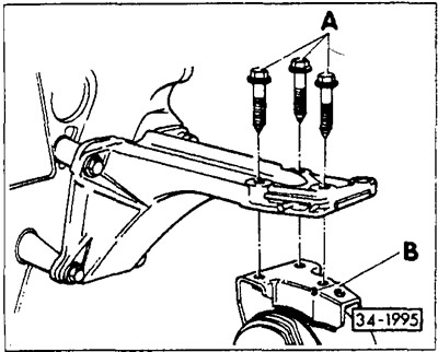
Remove 3 bolts -A- at right engine mount -B-.
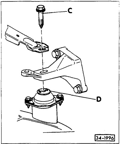
Remove hexagon bolt -C- at gearbox support -D-.
Caution: On vehicles with a brake booster, carefully press the hydraulic lines to the side to gain access to the bolt. On vehicles with anti-lock braking system, the coolant expansion tank must be removed if necessary.
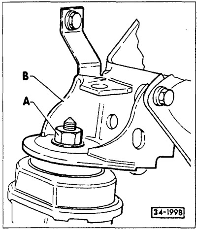
Loosen nut -A- for front retaining bracket -B-.
Check that all hoses and wires from the engine to the body have been removed. After that, remove the engine together with the gearbox.
Attention: When removing the engine, drive carefully so as not to damage the bodywork.
Separate the engine from the gearbox, for which remove the partition at the propeller shaft flange. Unscrew the bolts securing the engine / gearbox and partitions to the gearbox housing
Installation
Check engine mounts, coolant, oil and fuel hoses for porosity and cracks, replace if necessary.
Check the thickness and condition of the linings of the clutch drive plate. When the wear limit is reached or the vehicle has a high mileage, replace the clutch as a set. If the clutch release bearing makes noise when the clutch pedal is depressed, replace the bearing.
Clean the clutch release bearing and drive shaft spline and lightly lubricate with MoS grease2.
Check if there are bushings in the crankcase housing for centering the engine and gearbox, otherwise insert the bushings.
Put an intermediate plate on the centering sleeves and fix it on the engine crankcase at several points with a small amount of grease.
Carefully drive the engine into the engine compartment. When lowering the engine, be careful not to damage the drive shaft. clutch and body.
Screw in the engine mount with new self-locking nuts, but do not tighten them too much.
Carry out assembly in reverse order. Tighten the connecting bolts of the engine and gearbox with the following torques: M10 bolts - with a torque of 60 Nm; M12 bolts - torque 80 Nm. Tightening torques for engines with the designations ABN, EZ, RF and PG: M10 bolts with a torque of 45 Nm; M12 bolts - torque 55 Nm.
Carefully drive the engine with gearbox into the engine compartment. When lowering, make sure that the cardan shafts and body are not damaged.
When tightening the power unit supports, it is imperative to follow the sequence and prescribed tightening torques. Lubricate the threads and contact surfaces of the heads of the turned out bolts with engine oil before installation.
4 cylinder engine (except 16-valve) up to 9/93
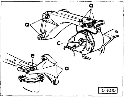
First tighten bolt -a- of rear engine support bracket to 25 Nm, then tighten bolt -e- of gearbox support bracket to 60 Nm. Tighten bolt -c- to 60 Nm.
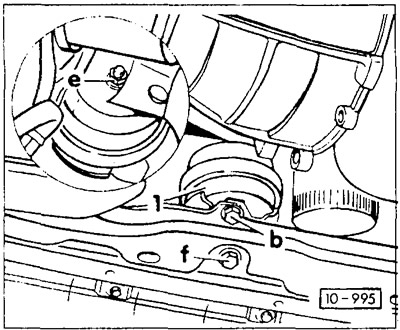
Screw on front engine support -1-. Tightening torques: e = 60 Nm, f = 70 Nm.
Attention: Torques for motors built from 10/93, see below.
Loosen the rubber-metal support of the engine bracket and console, align and tighten again by shaking without tension, see next chapter.
Attach shift cable to gearbox and adjust, see chapter «gear shifter».
Screw the speedometer shaft to the gearbox.
Hook up and adjust the clutch rod or screw on the clutch slave cylinder, see chapter «Clutch».
Screw the front exhaust pipe to the exhaust manifold fitting to 40 Nm and to the gearbox bracket to 25 Nm. Install the front baffle and grille, see chapter «Body». 9 If removed, screw on the A/C compressor and power steering pump. Tightening torques: compressor bracket to cylinder block, M8 bolts - tighten to 35 Nm; M10 bolts - tighten to 30 Nm; Tighten the booster pump connecting bolts to 20 Nm. Attach V-belt and tighten see later in this chapter.
Lower the car.
Connect the vacuum hoses to the intake manifold and carburetor in accordance with the markings. If required, secure them with screw clamps.
Attach and adjust throttle linkage, see chapters «Supply system» and «Petrol injection system».
Connect the fuel lines according to the markings and secure them with clamps.
Connect the electrical wires to the carburetor, temperature sensor, hydraulic switch and generator. Make sure that each plug is fixed and that the clip is in the correct position.
Fit coolant hoses and secure with clamps.
Check that all electrical wires, vacuum hoses, and coolant and fuel hoses are connected as marked. Secure the hoses with clamps. Fix electrical wires with clamps.
Install radiator, see chapter «Cooling system».
Diesel engine
Screw the fuel supply and return lines to the fuel pump. At the same time, do not frighten the hollow bolts in places, since they have unequal holes. The fuel return pipe mounting bolt is marked on the hex head «OUT». Incorrectly installed bolts may cause the following claims: insufficient engine power; foggy exhaust smoke in the full load area; the maximum speed of the crankshaft is not reached; at idle, the engine runs erratically.
Adjust the cold start thrust of the engine, see chapter «diesel engine».
Connect the electrical wires to the fuel switch and glow plugs.
Check start of fuel supply, see chapter «diesel engine».
Check the oil level in the engine and gearbox, top up if necessary.
Check the concentration of antifreeze in the coolant and top up if necessary, see chapter «Cooling system».
Install the air filter. Clean housing and filter and replace filter element if necessary, see chapters «Supply system» and «Petrol injection system».
Install and connect the battery.
Check ignition timing, adjust if necessary, see chapter «Ignition system».
Check idle speed, adjust if necessary.
Warm up the engine to normal operating temperature, check the oil and coolant levels again, and check all hose connections for leaks.
Check headlight adjustment and correct if necessary.
Engine and gearbox alignment
Alignment is necessary if the engine and gearbox were removed and the reinforced metal bearings of the front axle beam and engine bracket were released.
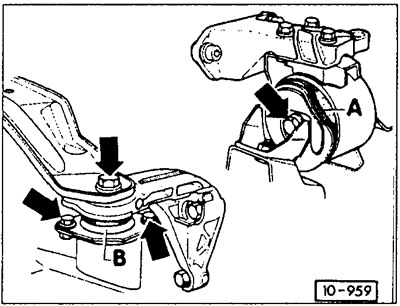
Until 9/93 (except 16-valve engine): Loosen the central bolt of the rail-metal support -A- (engine support).
16-valve engines from 12/88 to 9/93: instead of the right rubber-metal support (engine support) hydraulic support installed. To align the engine and gearbox, it is necessary to release the fastening of the hydraulic support to the front axle beam. The tightening torque of the hydraulic support on the front axle beam is 60 Nm; engine console to the engine and hydraulic support - 25 Nm.
From 10/93: Loosen the central bolt of the engine mount and the attachment to the front axle beam.
Release rubber-metal bearing (gearbox support) -B- at the gearbox and front axle beam.
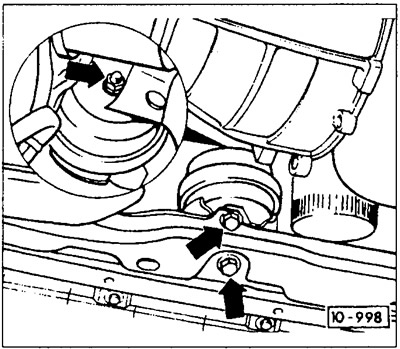
Release the front engine mount at the engine mount bracket and console.
Align the power unit without tension with shaking movements.
Tighten support bolts -A- and then support bolts -B- to the prescribed torque, see Fig. 10-959.
Tightening torques for engine mounts from 10/93
Tightening torques are for lubricated bolts. Values in brackets refer to 6-cylinder engines.
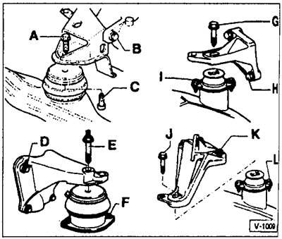
Front supports:
A - 55 Nm (60 Nm)
B - 55 Nm (60 Nm)
C - 50 Nm (55Nm)
Rear supports left (speed gearbox):
G - 50 Nm (60 Nm)
H - 25 Nm (25 Nm)
I - 30 Nm (25 Nm)
Rear supports right:
D —25 Nm (60 Nm)
E - 50 Nm (60 Nm)
F - 25 Nm (25 Nm)
Rear supports left (Automatic transmission):
J - 60 Nm
K - 25 Nm
L - 30 Nm
Attention: Different mounts for AAM and ABS motors.
Tightening torque of the front supports: nut A - 60 Nm, bolt C (short) - 35 Nm, bolt C (long) - 70 Nm.
Rear supports on the right: bolts E - 25 Nm, bolt A (in Figure 10-959) - 80 Nm, engine support in the lower figure - 60 Nm.
Visitor comments