



Contents: Examination ↓ 75hp engine with 10/94 (AAZ) ↓
The start of the injection pump can be checked both with the engine installed and removed from the vehicle. The check on the installed engine is described here. The check requires a linear movement dial indicator with a corresponding adapter for screwing into the injection pump. The start of the injection pump must be adjusted again after tensioning, removing or replacing the toothed belt, and after loosening the injection pump fastening or toothed wheels.
Note: For a 90 hp turbocharged engine, after the static adjustment described here, the injection start must be adjusted dynamically, i.e. with the engine running (workshop work, as it requires an electronic device). In a 110 hp turbocharged engine, the injection start can only be adjusted dynamically.
Instructions for the 75hp engine with 10/94 (AAZ) are given at the end of the section.
Prerequisites for verification:
- The timing belt is tensioned, the engine control is correctly adjusted, see. "Installing a timing belt".
- The cold start accelerator rod is fully retracted.
Examination
Turn the crankshaft to the TDC position for cylinder 1. Turn the crankshaft until the TDC mark on the flywheel and clutch housing boss, as well as the mark on the fuel injection pump gear and console, coincide. See. "Engine control adjustment".
Unscrew and remove the threaded plug in the high-pressure fuel pump.
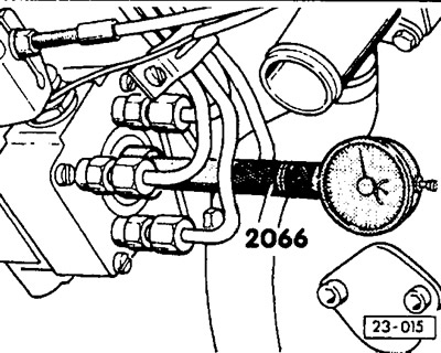
Screw in an adapter instead of a threaded plug (V.A.G-2066) and a pointer indicator (measurement range from 0 to 3 mm), until the indicator arrow starts to move. Set the indicator scale to "O". Then press the arrow indicator further until the arrow shows a value of 2.5 mm.
Note: For vehicles with 7/92, the 3313 adapter must be used for the dial indicator (modified plug thread M10x1).
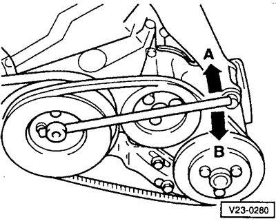
Using the SW19 12-point socket wrench, slowly turn the crankshaft against the direction of rotation (arrow A) until the indicator arrow stops moving.
Set the dial indicator scale to "0".
Turn the engine crankshaft in the direction of rotation (clockwise, arrow -B-), until the TDC mark on the flywheel coincides with the installation mark. The indicator should now show the control value.
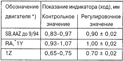
Correlation of engine designations and their parameters see at the beginning of the Guide.
Note: If the control value is within the specified tolerance, no new adjustment is required. If a new adjustment is to be made, the adjustment value must be set.
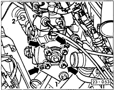
To adjust, loosen 3 bolts "2" securing the fuel injection pump to the console and bolt "1" securing it to the rear support.
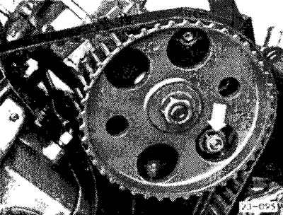
Loosen the lower and right bolts securing the console from the front through the hole in the fuel injection pump gear (arrow).
Check if the crankshaft is at TDC for cylinder 1, set it to TDC if necessary.
Set the prescribed value for the start of fuel supply by turning the high-pressure fuel pump.
Caution: If, when turning the high-pressure fuel pump, noticeable tension occurs in the high-pressure fuel lines, it is necessary to loosen the union nuts of the high-pressure fuel lines.
Tighten the fuel injection pump mounting bolts to a torque of 25 Nm.
Check again the start of fuel supply by turning the crankshaft back and forth.
If loosened, tighten the union nuts of the high-pressure fuel lines to a torque of 25 Nm.
Remove the dial indicator and tighten the threaded plug into the fuel injection pump cover with a torque of 15 Nm. If a leak is detected, tighten the plug with a torque of 25 Nm, no more.
Caution: Replace the sealing ring of the threaded plug with a new one each time.
Install the upper timing belt cover.
75hp engine with 10/94 (AAZ)
The start of fuel supply is checked and adjusted with the locking pin 3359 inserted into the gear wheel, when the engine crankshaft is in the TDC position for cylinder 1, see section above "Installing a timing belt".
If the locking pin does not fit, lock the camshaft, loosen the camshaft and injection pump gear fastenings and turn the injection pump gear hub to a position where the pin can lock it.
Check again that the crankshaft is at TDC for cylinder 1 and tighten the camshaft and injection pump gears, see above.
Turn the crankshaft in the direction of rotation by 2 turns and set it again to the TDC position for cylinder 1. Fix the fuel injection pump gear with a locking pin. If this is not possible, then loosen the mounting bolts and turn the fuel injection pump gear hub to a position in which the pin can fix it. In this position, tighten the fuel injection pump gear mounting bolts to a torque of 25 Nm.
Visitor comments