



Hydromechanical transmission car Volkswagen Passat B4

Features of the hydromechanical gearbox type 096
The 096 type hydromechanical gearbox with electronic control consists of an automatic gearbox and a torque converter. The selector lever on the body floor has seven positions: "P"...
The 096 type hydromechanical gearbox with electronic control consists of an automatic gearbox and a torque converter. The selector lever on the body floor has seven positions: "P"...

Features of the hydromechanical gearbox type 01
Fig. 4-58 shows the components of the 01 M type automatic transmission. The electronic control unit is installed on vehicles with 2E, ABS, 1Z, AFN engines manufactured since...
Fig. 4-58 shows the components of the 01 M type automatic transmission. The electronic control unit is installed on vehicles with 2E, ABS, 1Z, AFN engines manufactured since...

Removal and installation of automatic transmission type 096
To remove, place the vehicle on a lift. Disconnect the wire from the negative terminal of the battery. Disconnect the flexible speedometer drive shaft from the gearbox. Disconnect...
To remove, place the vehicle on a lift. Disconnect the wire from the negative terminal of the battery. Disconnect the flexible speedometer drive shaft from the gearbox. Disconnect...

Checking the gearbox oil level
Place the vehicle on a level, horizontal surface. Apply the parking brake. Set the selector lever to position "P". Start the engine at idle speed, remove the gearbox dipstick and...
Place the vehicle on a level, horizontal surface. Apply the parking brake. Set the selector lever to position "P". Start the engine at idle speed, remove the gearbox dipstick and...
Gearbox oil change
Warning: Use only Dexron ATF oil. The use of oil additives is prohibited. Place the vehicle on a lift, unscrew the gearbox oil drain plug and drain the oil, removing the dipstick...
Warning: Use only Dexron ATF oil. The use of oil additives is prohibited. Place the vehicle on a lift, unscrew the gearbox oil drain plug and drain the oil, removing the dipstick...

Checking the oil level in the differential housing
Remove the speedometer drive shaft and wipe it dry. Install the speedometer drive shaft, then remove it and check the oil level, which should be between the "Min" and "Max" marks...
Remove the speedometer drive shaft and wipe it dry. Install the speedometer drive shaft, then remove it and check the oil level, which should be between the "Min" and "Max" marks...

Checking the oil level and replacing the oil in the gearbox housing of type 096 CNK, 096 CRR, 096 CSK, 096 CNP and type 01M
Oil drain Remove the engine compartment protective tray. Place a container for drained oil under the gearbox. Unscrew the plug of the oil drain and inspection hole (Fig. 4-53)....
Oil drain Remove the engine compartment protective tray. Place a container for drained oil under the gearbox. Unscrew the plug of the oil drain and inspection hole (Fig. 4-53)....

Checking the oil level in the differential housing
To check the oil level in the differential housing, unscrew the inspection hole plug (Fig. 4-55). The oil in the differential housing is not replaced during the service life.
To check the oil level in the differential housing, unscrew the inspection hole plug (Fig. 4-55). The oil in the differential housing is not replaced during the service life.

Replacing the mesh filter
Replace the mesh filter (Fig. 4-56) each time the oil in the gearbox housing is changed. To remove the filter, remove the oil pan and the gearbox housing oil filler tube (Fig....
Replace the mesh filter (Fig. 4-56) each time the oil in the gearbox housing is changed. To remove the filter, remove the oil pan and the gearbox housing oil filler tube (Fig....
Checking the gearbox control drive
This adjustment is made on vehicles with a key removal lock for the instrument cluster switch and starter. Warning: Before starting work, with the engine running, set the selector...
This adjustment is made on vehicles with a key removal lock for the instrument cluster switch and starter. Warning: Before starting work, with the engine running, set the selector...
Checking the instrument switch and starter key extraction lock
Set the selector lever to position "P" and turn the switch key to the left until it stops. The key should only be removed in this position. Remove the key. The selector lever...
Set the selector lever to position "P" and turn the switch key to the left until it stops. The key should only be removed in this position. Remove the key. The selector lever...

Disassembly and assembly of the gearbox control drive
If it is necessary to replace the transmission control drive parts, remove the selector lever. When replacing the cable and other drive parts, there is no need to remove the...
If it is necessary to replace the transmission control drive parts, remove the selector lever. When replacing the cable and other drive parts, there is no need to remove the...
Adjustment of the transmission control cable of type 096 CNK, 096 CRR, 096 CSK, 096 CNP and type 01M
Remove the diagnostic connector, releasing it from its mount. Loosen the bolt securing the cable to the base of the selector lever. Move the selector lever through all positions...
Remove the diagnostic connector, releasing it from its mount. Loosen the bolt securing the cable to the base of the selector lever. Move the selector lever through all positions...

Differential
Fig. 4-59. Differential parts: 1 - differential box; 2 — driven gear of the main transmission; 3 - axle gears; 4 - satellites; 5 - satellite cup; 6 — main gear drive shaft; 7 -...
Fig. 4-59. Differential parts: 1 - differential box; 2 — driven gear of the main transmission; 3 - axle gears; 4 - satellites; 5 - satellite cup; 6 — main gear drive shaft; 7 -...

Electrical diagram of the hydromechanical gearbox control system
Fig. 4-61. Electrical diagram of the hydromechanical transmission control system: 1 — electronic control unit of the hydromechanical gearbox; 2 — KSUD controller; 3 — engine...
Fig. 4-61. Electrical diagram of the hydromechanical transmission control system: 1 — electronic control unit of the hydromechanical gearbox; 2 — KSUD controller; 3 — engine...

Adjusting the electromagnetic locking device of the selector lever
Adjust the position of the electromagnetic stopper by moving it along the mounting slots in such a way as to obtain a gap of 0.3 mm between the stopper pusher and the selector...
Adjust the position of the electromagnetic stopper by moving it along the mounting slots in such a way as to obtain a gap of 0.3 mm between the stopper pusher and the selector...

Removal, installation and adjusting the selector lever lock cable
Remove the selector lever handle. Remove the cover with the gear shift program switch and trim. Remove the center console. Loosen the stop bolt. Disconnect the locking cable from...
Remove the selector lever handle. Remove the cover with the gear shift program switch and trim. Remove the center console. Loosen the stop bolt. Disconnect the locking cable from...

Replacing differential output shaft seals
Place the vehicle on a lift. Loosen the bolts securing the front wheel drive shaft inner joint housing to the differential output shaft flange, move the drive shaft aside and hang...
Place the vehicle on a lift. Loosen the bolts securing the front wheel drive shaft inner joint housing to the differential output shaft flange, move the drive shaft aside and hang...

Adjusting the bearings of the main gear drive shaft-pinion
Note: The adjustment must be made in the order specified, since the torques of the bearings are adjusted taking into account the torques of all rotating parts of the gearbox....
Note: The adjustment must be made in the order specified, since the torques of the bearings are adjusted taking into account the torques of all rotating parts of the gearbox....
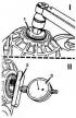
Adjusting the bearings of the main drive pinion
Using a 12 mm socket, tighten the threaded plug with an internal hexagonal socket for a key to a torque of 10 kgf·m, ensuring axial fixation of the bearings of the main drive...
Using a 12 mm socket, tighten the threaded plug with an internal hexagonal socket for a key to a torque of 10 kgf·m, ensuring axial fixation of the bearings of the main drive...

Adjusting the differential turning resistance moment
Lubricate the differential case bearings with gearbox oil. To correctly install the bearing rollers, use tool 3155 (Fig. 4-78) to tighten the bearing adjusting nuts to 15 kgf·m,...
Lubricate the differential case bearings with gearbox oil. To correctly install the bearing rollers, use tool 3155 (Fig. 4-78) to tighten the bearing adjusting nuts to 15 kgf·m,...
This section is available on russian, bulgarian, belarusian, ukrainian, serbian, croatian, romanian, polish, slovak, hungarian
Passat B6
Passat B5
Passat B4
Passat B3
Passat B2
- General information
- User manual
- Maintenance
- Petrol engine 1.6L
- Engine repair
- Cooling and lubrication system
- Fuel injection system
- Petrol engine 2.0L
- Engine repair
- Lubrication system
- Cooling system
- Fuel and exhaust systems
- Diesel engine 2.0L
- Engine repair
- Cooling and lubrication system
- Fuel and exhaust systems
- Transmission
- Clutch
- Mechanical gearbox
- Automatic gearbox
- Drive shafts
- Chassis
- Wheels and tires
- Car suspension
- Steering
- Brake system
- Body
- Exterior (external elements)
- Electrical equipment
- Power devices
- Lighting and appliances
- Electrical circuits
- General information
- User manual
- Weekly checks
- Maintenance
- Power unit
- Engine repair
- Cooling system
- Fuel system (petrol)
- Fuel system (diesel)
- Engine management
- Exhaust system
- Transmission
- Clutch
- Car gearbox
- Drive shafts
- Chassis
- Car suspension
- Wheels and tires
- Steering
- Brake system
- Body
- Exterior (external elements)
- Interior (internal elements)
- Doors and covers
- Ventilation and heating
- Electrical equipment
- Power devices
- Lighting and appliances
- Electrical circuits
- General information
- User manual
- Maintenance
- Technical data
- 8-valve engine
- Engine repair
- Cooling and lubrication system
- Supply system
- Ignition system
- Fuel injection «Mono-Jetronic»
- Control system «Mono-Motronic»
- Control system «Digifant»
- Control system «Simos»
- 16-valve engine
- Engine repair
- Cooling and lubrication system
- Fuel injection «K-Jetronic»
- Control system «KE-Motronic»
- Control system «Digifant»
- Diesel engine
- Engine repair
- Cooling and lubrication system
- Power and control system
- Turbocharging system
- Digital control system
- Transmission
- Clutch
- Manual gearbox
- Hydromechanical gearbox
- Front wheel drive
- Chassis
- Car suspension
- Steering
- Brake system
- Body
- Body elements
- Electrical equipment
- Power devices
- Lighting and appliances
- Electrical circuits
- General information
- User manual
- Driving Tips
- Maintenance instructions
- Technical data
- Power unit
- Engine repair
- Ignition system
- Lubrication system
- Cooling system
- Supply system
- Petrol injection system
- Diesel engine
- Exhaust system
- Transmission
- Clutch
- Car gearbox
- Chassis
- Suspension
- Steering
- Brake system
- Wheels and tires
- Body
- Exterior
- Interior
- Heating system
- Electrical equipment
- Power devices
- Lighting system
- Equipment and devices
- Wiper system
- Electrical circuits
- General information
- Introduction to instructions
- User manual
- Power unit
- Engines 4-cylinder FZ
- Engines 4-cylinder
- Engines 5-cylinder
- Transmission
- Clutch
- Four-speed gearbox
- Five-speed gearbox
- Hydromechanical gearbox
- Front wheel drive
- Chassis
- Front suspension
- Rear suspension
- Steering
- Brake system
- Body
- Body elements
- Electrical equipment
- Equipment and devices
- Electrical circuits