



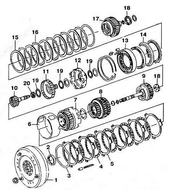
Fig. 4-58. Details of automatic transmission type 01M:
1 - torque converter;
2 — oil seal;
3 - retaining ring;
4, 15 - discs with internal engagement;
5, 16 — discs with external engagement;
6, 12 — drum;
7 — reverse clutch;
8, 9 — forward clutches;
10 — input shaft;
11 - crown gear;
13 — 1st gear freewheel clutch;
14 - pressure spring;
17 — satellite carriage;
18 — bearing;
19 - thrust needle bearings;
20 - radial needle bearing.
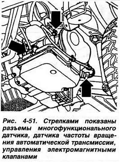
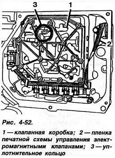
Depending on the information received, the control unit issues commands to the electromagnetic valves of the valve box (Fig. 4-52), the electromagnetic lock of the selector lever (with ignition on) and the starter interlock relay (with any gear engaged).
The control unit operates on fuzzy logic (or with deliberate inaccuracy), i.e. taking into account all the intermediate states that occur between the main states (0-1 in binary logic).
Thanks to this, the operation of the hydromechanical gearbox adapts to the driving style, engine characteristics and driving conditions (rolling resistance of wheels). The gearbox does not have "economical" and "sport" modes.
Electronic control unit 68-valve.
The applicability of gearbox types and their gear ratios are given in Tables 4-7 and 4-8.
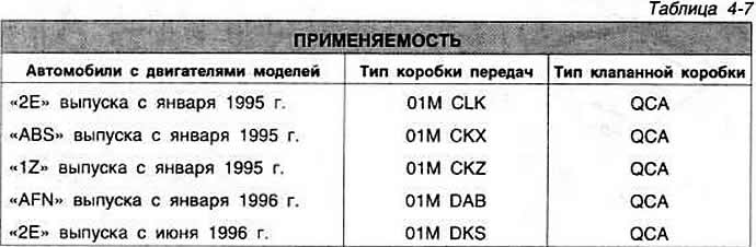
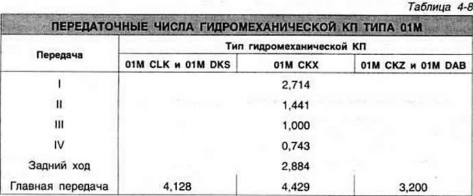
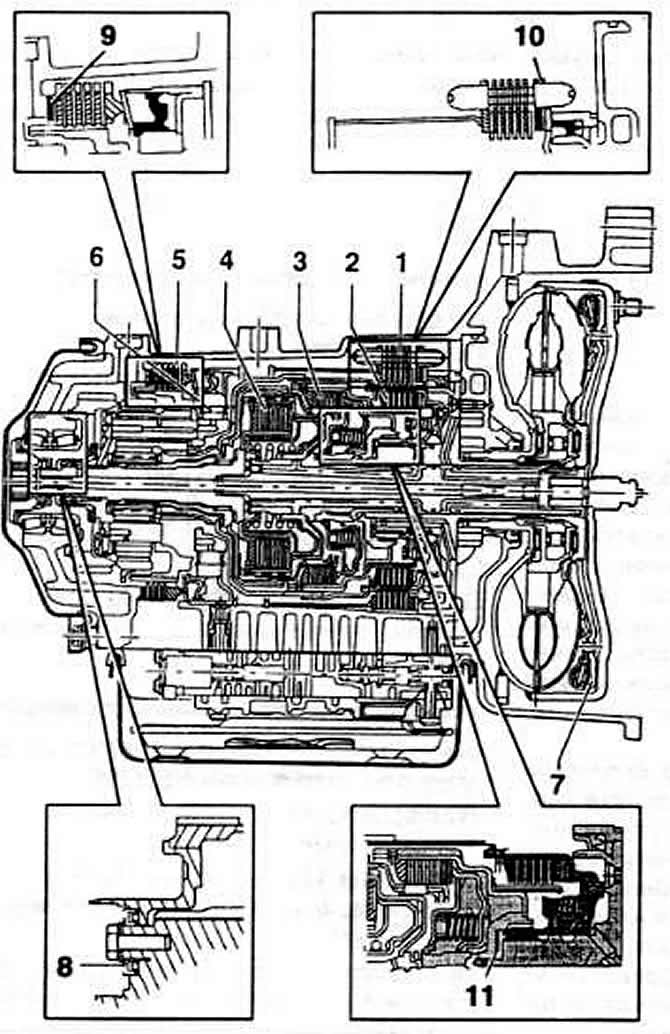
Fig. 4-60. Sectional view of the hydromechanical gearbox type 01M and installation locations of the adjusting rings:
1 — brake II and IV gears;
2 — reverse clutch;
3 - clutch for engaging 1st, 2nd and 3rd gears;
4 - clutch for engaging 3rd and 4th gears;
5 - reverse brake;
6 — freewheel clutch;
7 — direct transmission clutch;
8 — satellite cup adjustment ring;
9 — F1 reverse gear brake adjusting ring;
10 — brake adjustment ring II and IV gears F2;
11 — adjusting ring for clearance between clutches E1 and E2.
Visitor comments