



- "P" - parking;
- "R" - reverse;
- "N" — neutral;
- "D" - automatic shifting of all forward gears;
- "3" - automatic switching of I, II and III gears;
- "2" - automatic switching of 1st and 2nd gears;
- "1" — only 1st gear is engaged.
The center console of the passenger compartment contains a gear shift program switch with the "E" position (economical driving) and "B" (sport riding). When the "S" program is engaged, gear shifting occurs at a higher crankshaft speed, which results in faster acceleration of the vehicle. Program shifting can be performed both when the vehicle is stopped and when the vehicle is moving.
The types and applicability of gearboxes are given in Table 4-5.
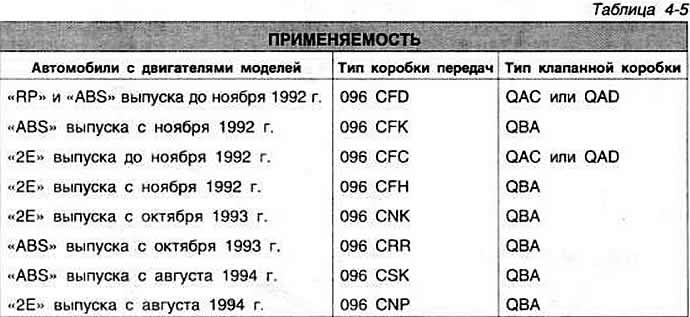
On cars manufactured since October 1992, a tapered roller bearing of reinforced design is installed. The design of the main gear pinion, gearbox housing, bolts, bearing cover, support ring, main gear pinion oil seal, inner and outer rings of the tapered roller bearing has also been changed. On cars manufactured since September 1995, the gearbox oil temperature sensor is included in the electronic control system of the hydromechanical gearbox.
The gearboxes of the previous and modified design differ in the threaded holes for the bolts for fastening the tapered roller bearing housing: since October 1992, M8 holes have been made for fastening the bolts for the reinforced roller bearing housing instead of M6.
The details of the automatic transmission are shown in Fig. 4-75.
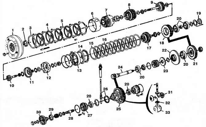
Fig. 4-75. Details of the automatic transmission type 096:
I - torque converter;
2 — oil seal;
3 - retaining ring;
4, 15 - discs with internal engagement;
5, 16 — discs with external engagement;
6, 12 — drum;
7 — reverse clutch;
8, 9 — forward clutches;
10 — input shaft;
11 - crown gear;
13 — 1st gear freewheel clutch;
14 - pressure spring;
17 — satellite carriage;
18 — main gear drive pinion;
19 - screw plug;
20 — bearings;
21 — driven gear of the main transmission drive;
22 — housing of the rear bearing of the main gear drive shaft-pinion;
23 - parking brake toothed retaining ring;
24 — main gear drive shaft;
25 — driven gear of the main transmission;
26 — speedometer drive;
27 — differential box bearing adjusting nut;
28 — differential output shaft;
29 — differential output shaft flange seal;
30 — differential output shaft flange;
31 - semi-axial gears;
32 - satellites;
33 - satellite cup.
Gear ratios of gearboxes are given in Table 4-6.
[View the original on this portal: www.VWManual.ru]
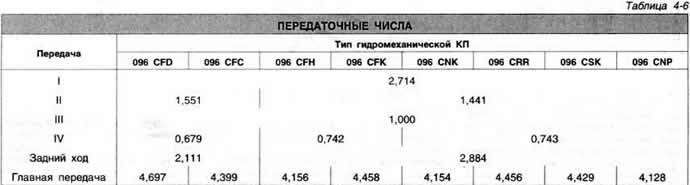
On cars produced since November 1992, hydromechanical gearboxes with modified gear ratios and a modified gear shift program are installed, designated by indexes "CFF", "CFH", "CFK" and "CHG". They do not have the E122 program switch, the functions of which are performed by the J217 control unit (microcomputer).
The design of the E1 and E3 clutches and the planetary gear components has also been changed. The components of the changed and previous design are not interchangeable.
Visitor comments