
Disassembly
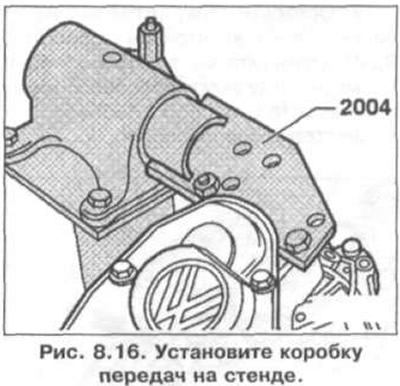
1. Install the gearbox on the stand (pic. 8.16).
2. Drain the gearbox oil.
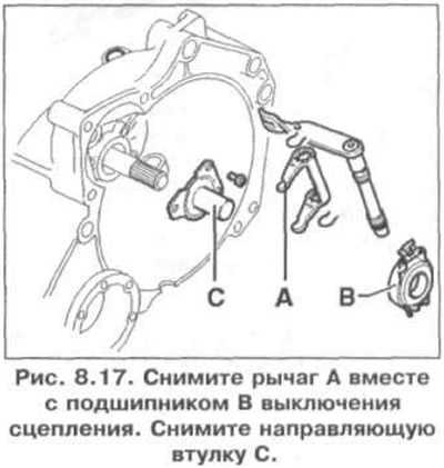
3. Remove lever A together with clutch release bearing B (pic. 8.17). Remove guide bush C.
4. Remove the flanges of both axle shafts.
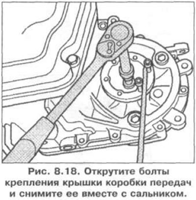
5. Turn off bolts of fastening of a cover of a transmission and remove it together with an epiploon (pic. 8.18).
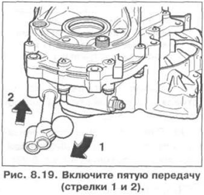
6. Engage fifth gear (arrows 1 and 2) (pic. 8.19).
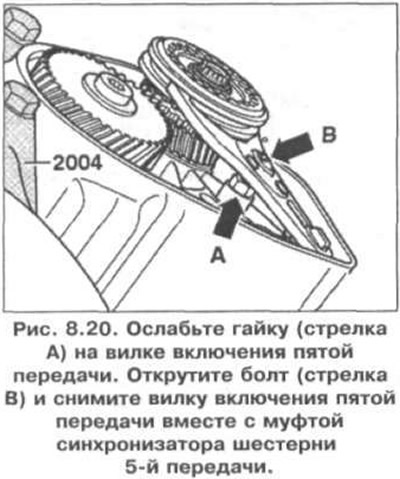
7. Loosen the nut (arrow A) on the fifth gear fork (pic. 8.20). unscrew the bolt (arrow B) and remove the 5th gear shift fork along with the 5th gear synchronizer clutch.
8. Install the synchronizer sleeve back onto the synchronizer hub.
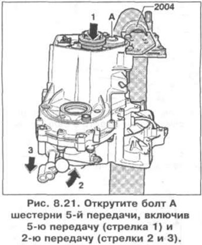
9. Remove bolt A of the 5th gear by engaging 5th gear (arrow 1) and 2nd gear (arrows 2 and 3) (pic. 8.21). After the inclusion of these two gears, both shafts of the gearbox are blocked. Remove the 5th gear synchronizer hub and disengage 2nd gear.
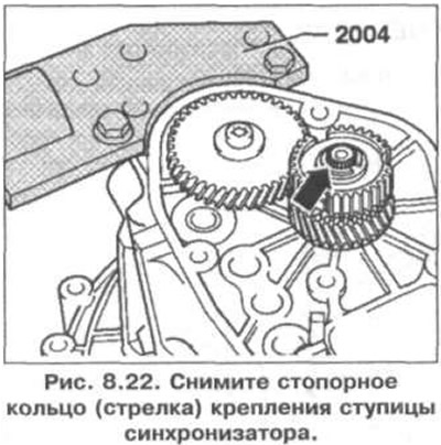
10. Remove retaining ring (arrow) synchronizer hub mountings (pic. 8.22).
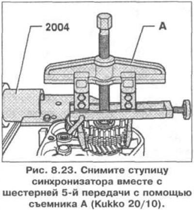
11. Remove the synchronizer hub together with the 5th gear using puller A (pic. 8.23).
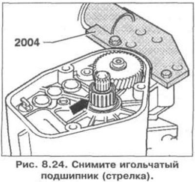
12. Remove the needle bearing (arrow) (pic. 8.24).
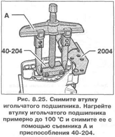
13. Remove the needle bearing bush (pic. 8.25). Heat the needle bearing bush to about 100°C and remove it using puller A and tool 40-204.
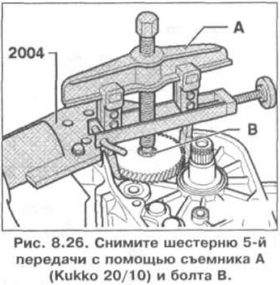
14. Remove the 5th gear with puller A (Kukko 20/10) and bolt B (pic. 8.26).
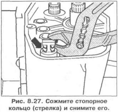
15. Squeeze the circlip (arrow) and take it off (pic. 8.27). Loosen the clutch housing bolts.
16. Remove the clutch housing.
17. Remove the differential case.
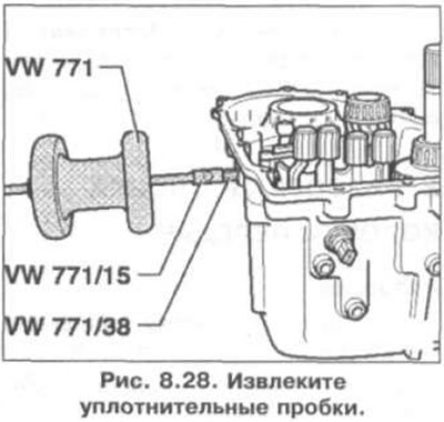
18. Remove sealing plugs (pic. 8.28).
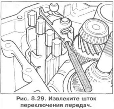
19. Remove the shift rod, if necessary, use a punch (pic. 8.29).
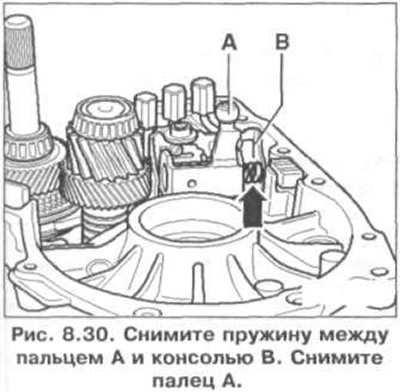
20. Remove spring between pin A and console B (pic. 8.30). Remove finger A.
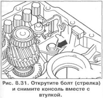
21. Remove the bolt (arrow) and remove the console together with the sleeve (pic. 8.31).
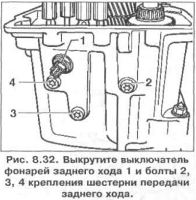
22. Unscrew the reverse light switch 1 and bolts 2, 3, 4 fastening the reverse gear (pic. 8.32).
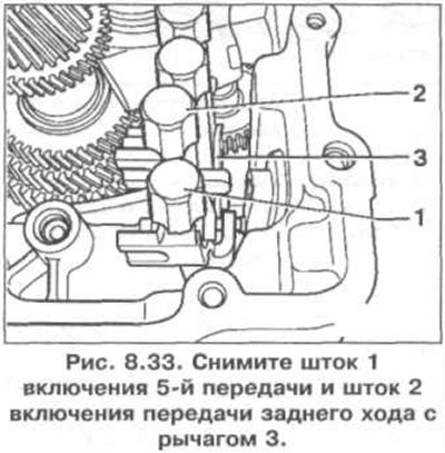
23. Remove the stem 1 of the 5th gear and the stem 2 of the reverse gear with lever 3 (pic. 8.33).
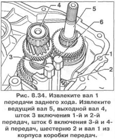
24. Remove shaft 1 reverse gear (pic. 8.34). Remove drive shaft 5, output shaft 4, 1st and 2nd gear engagement rod 3, 3rd and 4th gear engagement rod 6, gear 2 and shaft 1 from the gearbox housing.
Installation
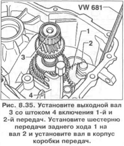
25. Install output shaft 3 with rod 4 for engaging 1st and 2nd gears (pic. 8.35). Install reverse gear 1 onto shaft 2 and install shaft into gearbox housing.
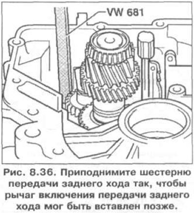
26. Raise the reverse gear so that the reverse gear lever can be inserted later (pic. 8.36).
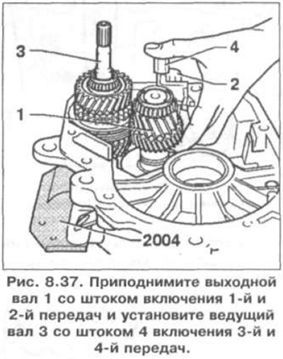
27. Raise the output shaft 1 with the 1st and 2nd gear engagement rod and install the drive shaft 3 with the 3rd and 4th gear engagement rod 4 (pic. 8.37).
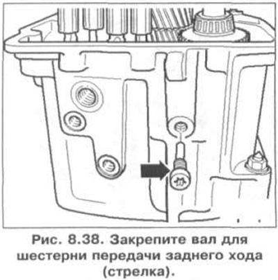
28. Fix the reverse gear shaft (arrow) (pic. 8.38).
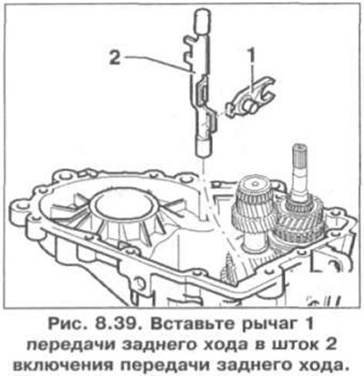
29. Insert the lever 1 of the reverse gear into the rod 2 of the reverse gear (pic. 8.39). Install them as an assembly, but first insert the lever into the reverse gear.
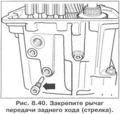
30. Secure the reverse gear lever (arrow) (pic. 8.40).
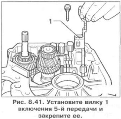
31. Install fork 1 for 5th gear and secure it (pic. 8.41).
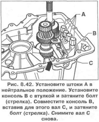
32. Set rods A to neutral position (pic. 8.42). Install console B with bushing and tighten bolt (arrow). Align console B by inserting shaft C for this, and tighten the bolt (arrow). Remove shaft C again.
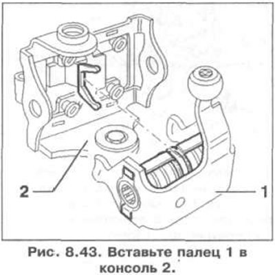
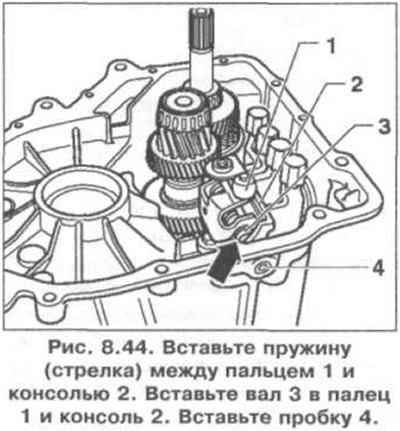
33. Insert finger 1 into console 2 (pic. 8.43).
34. Insert the spring (arrow) between finger 1 and console 2 (pic. 8.44). Insert shaft 3 into pin 1 and console 2. Insert plug 4.
35. Attach differential.
36. Install the gearbox housing.
37. Establish the switch of lanterns of a backing.
38. Install the springs, thrust washers, cone rings and axle shaft flanges. Between the flanges of the axle shafts there is a difference in diameter (pic. 8.45).
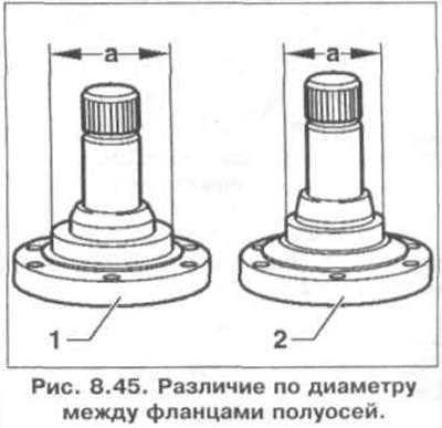
The difference in diameter between the flanges of the axle shafts
| Designation | shaft flange | Distance «A» |
| 1 | Left flange, gearbox side | 57 mm |
| 2 | Right flange, clutch side | 48 mm |
39. Further installation is carried out in the reverse order of removal.
Visitor comments