



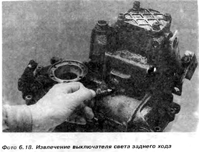
2. Unscrew and remove the bolt securing the selector shaft assembly (photo 6.19).
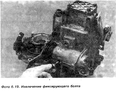
3. Unscrew the nut and remove the lever from the shaft, note that the installation of the lever on the shaft is possible only in one position (photo 6.20).
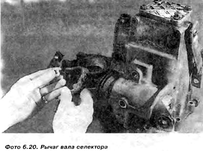
4. Remove the rubber cover of the selector shaft (photo 6.21).
View the original on the website (VWMANUAL)
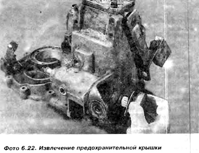
5. Unscrew the cover protecting the selector shaft assembly (photo 6.22).
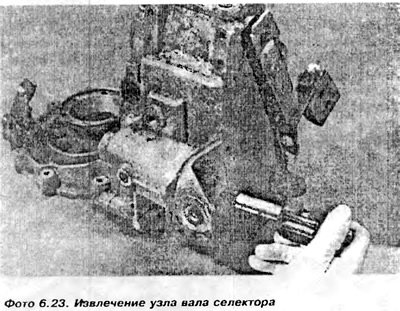
6. Set the gap in the gearbox with the selector shaft and in this position knock out the unit in the direction of the larger hole (photo 6.23)
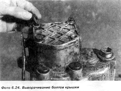
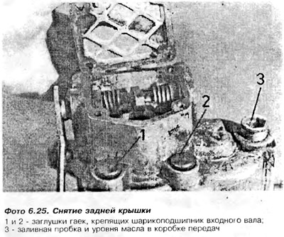
7. Loosen the bolts and remove the rear cover of the gearbox (photo 6.24 and 6.25).
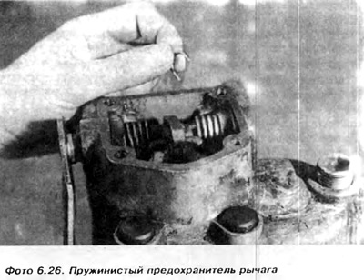
8. Remove the spring-loaded push rod lever guard (photo 6.26).
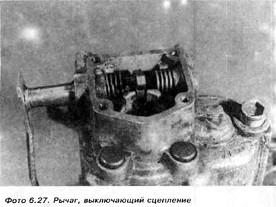
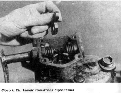
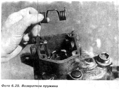
9. Pull the clutch release lever out of the housing (photo 6.27), while removing the clutch pusher lever (photo 6.28) and the return spring (photo 6.29)
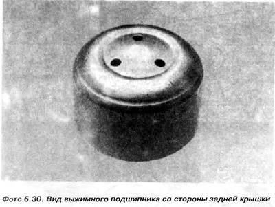
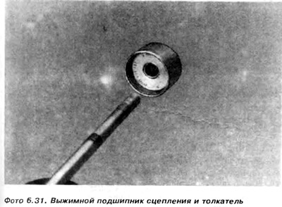
10. Remove the release bearing, clutch and push rod (photo 6.30 and 6.31).
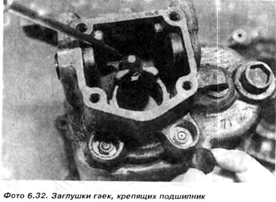
11. Lift and remove the plugs, then unscrew the three nuts securing the input shaft ball bearing (photo 6.32).
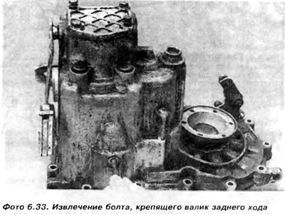
12. Unscrew and remove the bolt securing the reverse shaft (photo 6.33).
13. Lift and remove the plastic cap from the center of the left drive flange. Bend the drive flange using a tightening tool and remove the spring ring and washer (photo 6.34). Then remove the flange (photo 6.35).
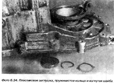
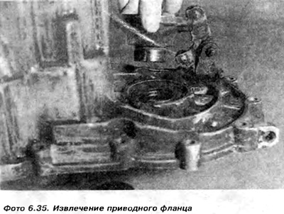
It is necessary to pay attention that the washer under the spring ring is placed with the concave side towards the drive flange.
Under the drive flange is a spring, a spring plate and a conical bronze ring. This ring is cone-shaped towards the main gear pinion.
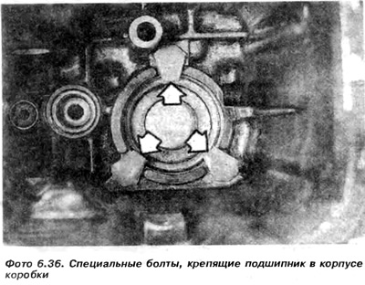
14. Loosen the bolts that connect the main gearbox housing to the clutch housing, and then use a tightener to pull the main housing off the bearing on the clutch shaft. Remove the bearing spacer washer (if any), special bolts securing the bearing and remove the magnet from the clutch housing (photo 6.36).
15. Remove the slider and fork assembly (figure 6.9).
16. Remove the reverse gear together with the gear.
17. Remove the 4th gear retaining ring on the output shaft, then remove the 4th gear using a tightener if necessary.
18. Only after removing the 4th gear from the output shaft can the clutch shaft assembly be removed as a whole -!!!!
19. Remove the slider from the clutch housing and pull the fork assembly 17 to the side (figure 6.9).
20. Remove the input shaft assembly from the clutch housing
21. Remove the 3rd gear retaining spring ring from the output shaft and then remove; 3rd and 2nd gear pinions, 2nd speed synchronizer ring, needle bearing
Using a puller installed under the first speed gear, remove the following elements: the inner race of the needle bearing of the second speed gear, the synchronizer hub with the reverse gear, which is simultaneously the movable clutch of the 1st and 2nd speeds, called the movable gear, the first speed synchronizer ring, the first speed gear with the needle bearing (a long-armed tightener will be needed).
22. Remove the socket spacer washer 1, which rests on the disc securing the bearing. The washer faces the cone bearing with its concave side.
23. Loosen bolts 25 and remove the disc securing the bearing, and remove the output shaft from the clutch housing.
24. Remove the remaining drive flange, then remove the differential mechanism assembly. It is better to entrust the differential mechanism repair to specialized workshops and not to perform it yourself.
25. No special tool is required to repair the clutch housing, and the actions are similar to those described in paragraph 4. A sleeve 6 is pressed into the clutch housing (figure 6.10). It can be lifted with a screwdriver, but care must be taken not to damage the housing. After removal, the bushing must be replaced with a new one. The new bushing is pressed into place using the appropriate tubular punch.
26. If it is necessary to replace the cone bearings of the output shaft or differential mechanism, please note that the small and large bearings fix the position of the output shaft in relation to the main gear pinion. The corresponding installation is carried out using a distance washer, which is selected from 16 available washers of different thicknesses.
The washer is inserted between the outer ring of the smaller cone bearing and the clutch housing. If either bearing is faulty, both must be replaced. During replacement, the old bearings break. The new bearings are installed by pressing in, and a suitable spacer must be installed under the smaller bearing.
27. This operation is quite complex and requires measuring the longitudinal clearance of the output shaft using a clock gauge, as well as correctly determining the traces of the teeth of the helical gears. Cone bearings must be pre-stressed. The correct pre-stress is assessed by measuring the torque required to rotate the output shaft. The greater the pre-stress, the greater the torque required to rotate.
Note: It is important to note that the input shaft spacer washer and the longitudinal clearance measured on the spring ring securing the 3rd gear to the output shaft are mutually dependent. This means that a new spacer washer and spring ring must be installed.
There are 6 different spring rings, differing in thickness. If you do not have sufficient experience and the appropriate tools, the bearings should be replaced at a specialized gearbox repair facility.
28. It is important to remember that the input shaft ball bearing must be pressed into the gearbox housing with the wider ring of the inner race in the direction of the 4th speed gear. If a spacer was installed, it must be placed in the housing before pressing the bearing into the housing. Then insert the bolts securing the bearing and tighten the nuts
29. Input and output shaft assemblies can be repaired as described in the next paragraph.
30. Inspection and maintenance of the differential mechanism is described in paragraph 7.
However, it is necessary to pay attention to the following differences concerning the 020 gearbox.
a) When determining the size of the distance washer, we assume that the thickness of the washer is equal to A + 0.40 mm.
b) We insert a 1 mm thick spacer washer into the clutch housing of the gearbox, and the spacer adjusting washers into the main housing of the gearbox.
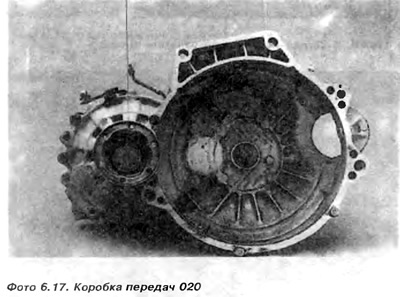
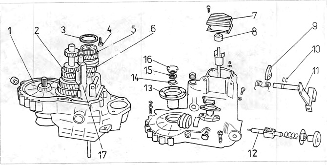
Figure 6.9. Gearbox 020, 4-speed
1 - large main gear pinion; 2 - output shaft, 3 - spacer washer between the bearing and the gearbox housing; 4 special bolt securing the input shaft bearing; 5 - bearing; 6 - input roller; 7 - back cover; 8 - clutch release bearing; 9 - clutch pusher lever; 10 - spring rings; 11 - switch-off lever; 12 - shaft; 13 - drive flange; 14 - concave washer; 15 - pressure ring; 10 - plastic plug; 17 - fork assembly with slider.
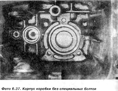
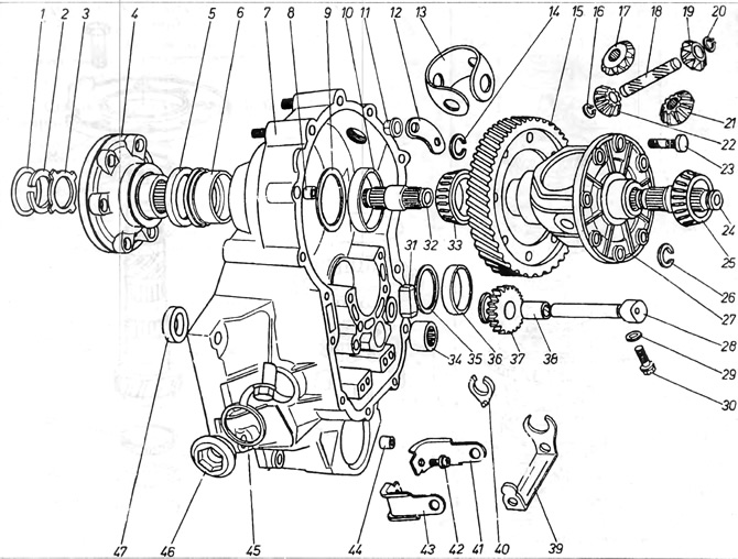
Figure 6.10. Differential mechanism 020
1 - plastic plug; 2 - spring ring; 3 - concave washer; 4 - drive flange; 5 - flange seal; 6 - seal bushing; 7 - clutch housing; 8 - fixing pin; 9 - washer; 10 - bearing track; 11 - nut; 12 - washer; 13 - clip; 14 - spring ring; 15 - large main gear; 16 - spring ring; 17 - satellite; 18 - satellite shaft; 19 - satellite; 20 - spring ring; 21 - satellite; 22 - satellite; 23 - bolt securing the large pinion of the main transmission to the differential mechanism basket; 24 - short axle shaft; 25 - cone bearing; 26 - spring ring; 27 - satellite basket; 28 - reverse gear shaft; 29 - washer; 30 - bolt; reverse gear retaining roller; 31 - magnet; 32 - short axle shaft; 33 - tapered bearing; 34 - input shaft needle bearing; 35 - spacer washer; 36 lower cone bearing track; 37 - reverse gear; 38 - Reverse gear bushing; 39 - reverse gear forks; 40- plastic fork insert; 41 - support for laying forks; 42 - fastening bolt; 43 - support for laying forks; 44 - fixing peg; 45, 46 - TDC hole plug; 47 - washer.
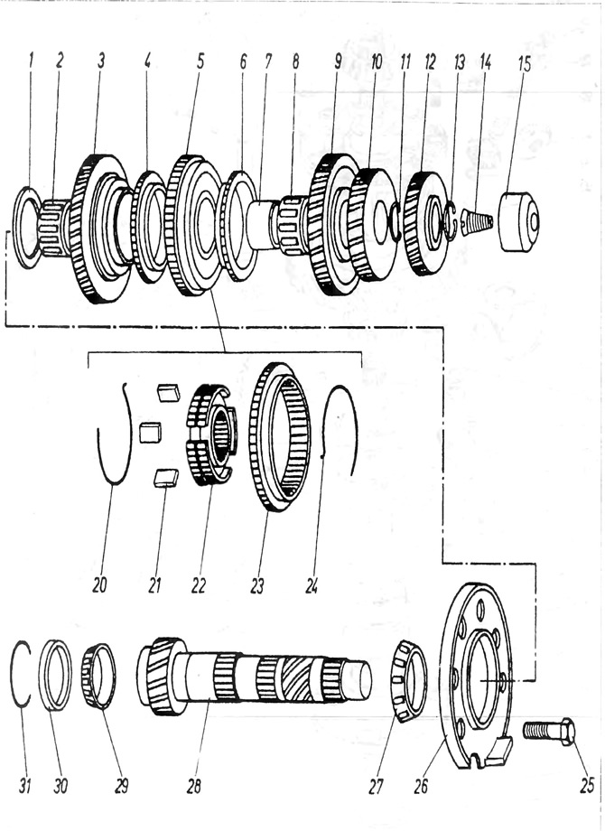
Figure 6.11. Output shaft box 020, 4-speed
1 - concave washer; 2 - 1st gear needle bearing; 3 - 1st gear pinion; 4 - synchronizer ring; 5 - 1st and 2nd speed synchronizer unit; 6 - synchronizer ring; 7 - needle bearing track; 8 - needle bearing; 9 - 2nd speed gear; 10 - 3rd gear pinion; 11 - spring ring; 12 - 4th speed gear; 13 - spring ring; 14 - screw securing the needle bearing in the gearbox housing; 15 - needle bearing; 20 - ring supporting crackers 21 - crackers; 22 - synchronizer hub; 23 - movable gear with reverse gear; 24 - ring that holds the crackers; 25 - bearing disc mounting bolt; 26 - bearing disc; 27 - cone bearing; 28 - output shaft; 29 - lower cone bearing; 30 - lower bearing track; 31 spacer washer for the lower bearing track.
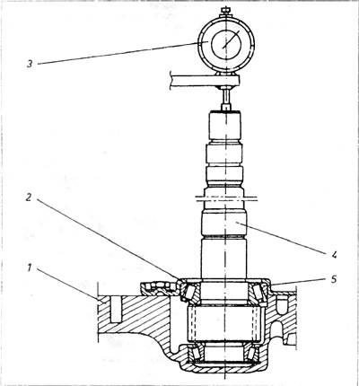
Figure 6.12. Measuring the longitudinal clearance of the output shaft
1 - clutch housing; 2 - bearing disc; 3 - hour sensor; 4 - output roller; 5 - upper cone bearing.
Visitor comments