



2. Install the cone ring into the differential mechanism bearing and install the right drive flange, put the washer with the concave side towards the flange and install the pre-ring and plastic plug.
3. Install the output shaft together with the cone bearings into the clutch housing and mate it with the final drive gear.
4. Install the bearing mounting plate and tighten the bolts.
5. Install the 1st speed gear spacer washer on the output shaft with the concave side facing the cone bearing.
6. Install the needle bearing and 1st speed gear and then the first synchronizer ring. Press in the assembled 1st and 2nd speed synchronizer, making sure that the crackers are in the cutouts of the synchronizer ring. Before installation, the synchronizer must be heated to 120°C.
7. Install the reverse shaft together with the toothed gear, install the reverse gear forks, serrating them with the reverse gear.
8. Using a metal tube, tap the inner race of the 2nd speed gear needle bearing, then install the needle bearing, synchronizer ring and 2nd speed gear.
9. Heat the 3rd gear pinion and press it onto the output shaft. Select and install a new spring ring. The selected spring ring should be the thickest but one that would completely fit into the shaft groove and eliminate the longitudinal clearance of the 3rd gear pinion. Spring rings vary in thickness and are marked with different colors.
10. Install the input shaft into the clutch housing and align it with the output shaft.
11. Heat the 4th speed gear and press it onto the output shaft. Put on the spring ring.
12. Install the slider shaft spring into the clutch housing, then secure the slider assembly. To do this, install the 1st and 2nd speed slider into the clutch groove, then install. The 3rd and 4th speed slider and the reverse slider are engaged with the reverse forks (photo 6.58 and 6.80).

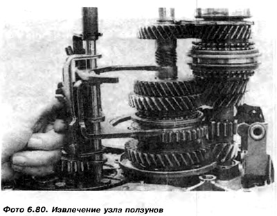
13. Install the slider shaft into the clutch housing and set the notches in the forks in the neutral position.
14. The clutch housing and shafts are ready for installation of the main gearbox housing.
15. Check the position of the reverse shaft (figure 6.19).
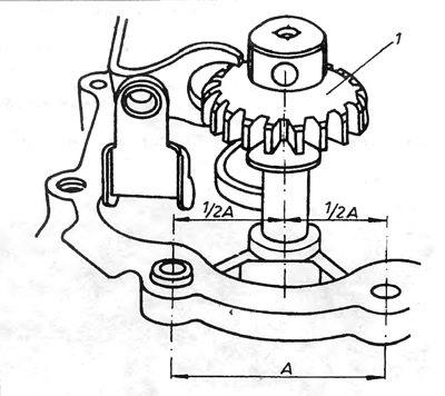
Figure 6.19. Position of the bolt hole securing the shaft in relation to the holes in the clutch housing
1 - reverse gear.
16. Place the new gasket on the clutch housing seal and make sure the magnet is in place.
17. Install the main gearbox housing onto the shafts and the slider shaft, and then drive the ball bearing onto the input shaft using a metal tube, while simultaneously supporting the shaft on a block of hard wood.
18. Screw in and tighten the reverse shaft fixing bolt, then screw in and tighten the bolts connecting the main gearbox housing to the clutch housing.
19. Check the tightening of the bolts of the input shaft ball bearing mounting plate.
20. Install the support washer 26, 5th speed gear on the input shaft with the phase in the direction of the bearing, and then the needle bearing 23 (figure 6.20).
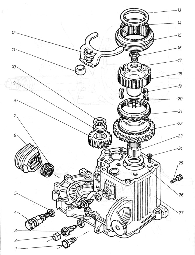
Figure 6.20. Fifth gear 020
1 - selector shaft assembly fixing bolt; 2 - plug; 3 - selector shaft dog, used in four-speed gearboxes; 5 - washer; 6 - rubber cover of the selector shaft; 7 - selector shaft seal; 8 - 5th gear pinion; 9 - washer; 10 - spring ring; 11 - slider bushing; 12 - 5th speed forks; 13 - protective tin plate; 14 - spring ring; 15 - 5th speed synchronizer sliding clutch; 16 - bolt securing the synchronizer unit; 17 - washer; 18 - synchronizer hub; 14 - cracker, 20 - spring ring 21 - synchronizer ring; 22 - 5th speed gear; 23 - needle bearing; 24 - bolts securing the ball bearing plate; 25 - bolt securing the reverse shaft; 26 - washer; 27 - main gearbox housing.
21. Heat the 5th speed gear 8 to 100°C and press it onto the output shaft so that the notch visible on the side surface of the gear is on the side of the rear cover of the gearbox.
22. Install the support washer 9 and the new spring ring 10 on the output shaft.
23. With the forks installed in the groove of the coupling 15, place the gear 22, the synchronizer ring 21 and the synchronizer on the main shaft, the slider sleeve 11 together with the locking plate.
24. Without moving the slider, screw in the slider tube (clockwise) into the forks 12, until it protrudes 5 mm above the forks. It is necessary to pay attention not to remove the slider shaft from the tube during this operation, since otherwise the sliders inside the gearbox will fall apart and it will be necessary to remove the gearbox housing to reinstall them on the shaft.
25. Cover the thread of the fastening bolt 16 with a blocking substance and screw it into the input shaft. Engage fifth gear and reverse gear through the hole in the selector shaft, then tighten the bolt to the specified torque.
26. Engage neutral gear and insert the selector shaft assembly. For this operation, it is best to place the gearbox on its side so that the selector shaft can be lowered into place vertically. Before doing this, check that the sockets in the sliders are installed evenly (for four-speed gearbox) (photo 6.58 or 6.123).
27. Put on the spring and press the selector shaft cover (using a spark plug wrench).
28. Install and press the reverse light switch.
29. Screw in the selector shaft assembly fixing bolt.
30. Check the reliability of fifth gear engagement. If necessary, adjust by screwing or unscrewing the 5th gear slider tube.
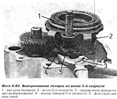
31. Support the forks with a pair of flat keys (19mm and 24mm) or another suitable tool with a thickness of approximately 12 mm and drive in the fixing plate 5 (photo 6.62).
32. Put on the new rear cover gasket and then put on the cover (with release bearing) and tighten the fastening bolts.
33. Install the left drive flange, then the spring washer, spring ring and plastic plug.
34. Lubricate the clutch pusher and insert it into the input shaft.
35. The gearbox assembly is now complete. Now you need to engage each gear in turn to check that they are engaged correctly.
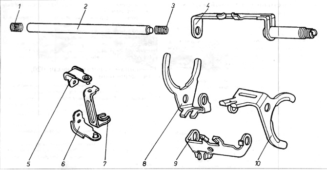
Figure 6.17. Disassembled slider assembly
1 - slider shaft spring; 2 - slider shaft; 3 - spring; 4 - 5th speed slider; 5 and 6 - support for laying forks; 7 - reverse forks; 8 - gear slider for 1st and 2nd gears; 9 - reverse slider; 10 - 3rd and 4th speed gear slider.
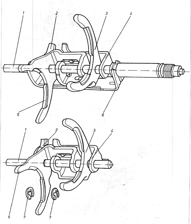
Figure 6.18. Sliding unit of the 020 gearbox, 4- and 5-speed
1 - shaft of the slider assembly; 2 - socket for engaging the reverse forks; 3 - 3rd and 4th speed slider; 4 - reverse slider; 5 - 1st and 2nd speed slider; 6 - 5th speed slider; 7 - safety ring (only in 4-speed gearbox)
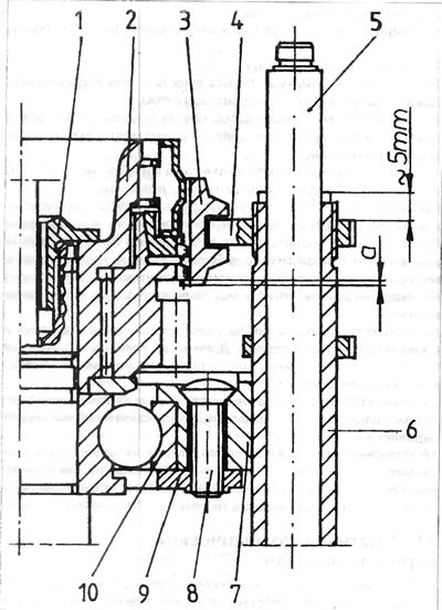
Figure 6.21. Fifth gear synchronizer
1 - bolt securing the synchronizer unit; 2 - synchronizer hub; 3 - movable clutch; 4 - 5th gear forks; 5 - roller of the slider assembly; 6 - slider tube; 7 - bearing hub; 8 - rivet; 9 - plate; 10 - bearing, a = 1 mm.
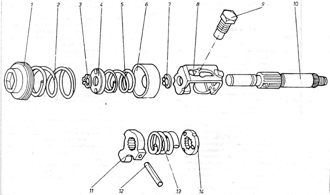
Figure 6.22. Selector shaft assembly 020
1 - lid; 2 - spring; 3 - spring ring; 4 - small spring plate; 5 - inner spring; 6 - large spring plate; 7 - spring ring; 8 - distribution lever housing; 9 - fixing bolt, 10 - selector shaft; 11 - distribution lever; 12 - spring release peg; 13 - spring; 14 - peg dog plate.
[The original information is posted on the website: VWManual]
Visitor comments