
Short description
For these vehicles, the gearbox can be removed individually downwards. The engine remains installed in the car.
For Touareg with all engine variants, it is recommended to remove the lower engine/gearbox bolts before removing the power unit. If possible, install the torque converter mount in advance. This advice applies to both removal and installation of the gearbox.
Removing
Remove the engine cover.
NOTE: Figure 3.28 shows the tandem pump from below with the motor removed.
Fasten the 20mm thick wood spacer 1 with adhesive tape 2 as shown on the tandem pump (pic. 3.28).
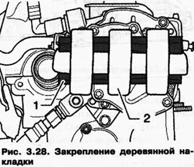
If a wooden spacer that is too thin is used or no wood spacer is used, the gearbox may lie on the subframe during further dismantling and the gearbox cannot be removed.
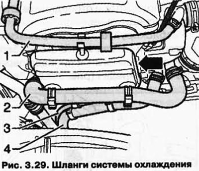
Remove the cooling system hoses 1-4 from the noise insulation on the front side of the engine (pic. 3.29).
Unscrew the soundproofing (3 bolts).
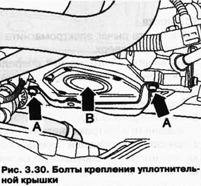
Remove bolts A and remove the noise insulation holder.
Remove the sealing cap B with a 10-221 puller from the sealing flange (pic. 3.30).
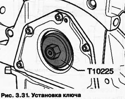
Screw the key T10225 to the crankshaft (pic. 3.31).
Be sure to follow the battery disconnection sequence.
Disconnect the ground terminal from the battery. with the ignition off.
Completely remove the engine/transmission soundproofing.
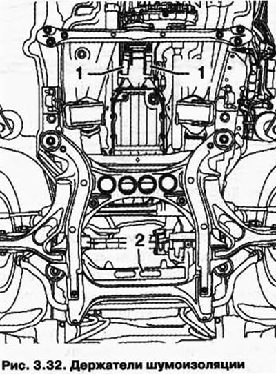
Remove noise insulation holders 1 and 2 (pic. 3.32).
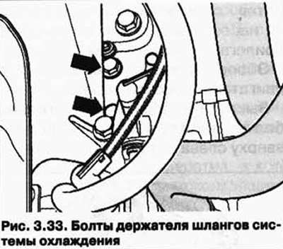
Unscrew the bolts of the holder of the hoses of the cooling system on the right engine mount (pic. 3.33).
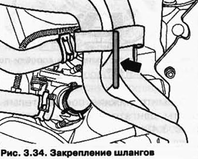
Pull the coolant hoses up as shown and secure, for example, with welding wire on the right engine mount (pic. 3.34).
Loosen the torque converter/driven plate bolts (6 pcs.).
Turn the torque converter/driven plate through the engine crankshaft using the T10225 1/3 turn (120°) in the direction of rotation of the motor shaft (pic. 3.31).
Remove the lock washer 1 and the selector rod 2 by hand from the shift lever (rice. 3.11).
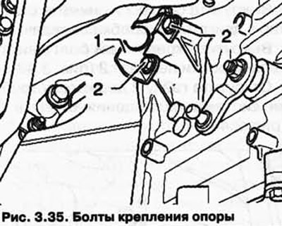
Remove bolts 2 and remove support 1 (pic. 3.35).
Remove the ATF pipes from the gearbox (pic. 3.36).
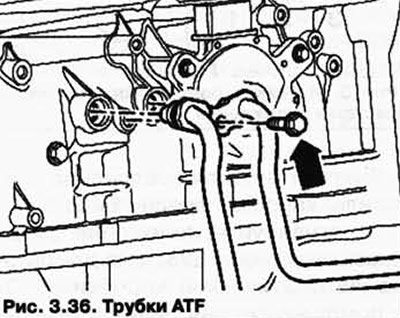
Close the ATF pipes and transmission openings with clean plugs.
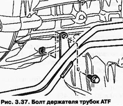
Unscrew the ATF pipe holder bolt on the gearbox (pic. 3.37).
Remove the engine/transmission mounting bolt before lowering the power unit (pic. 3.38).
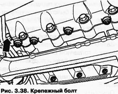
Dismantling the bolt with the box lowered is not possible due to lack of space.
Remove the transfer box.
Remove the exhaust pipe with the catalyst.
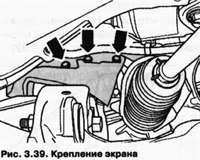
Remove the screen (pic. 3.39).
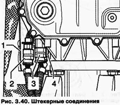
Remove shield 1, unlock and disconnect plug connections 2-4 (pic. 3.40).
Lower the gearbox a little more as follows.
Install the tip of the jack C in the engine and gearbox rack VA G 1383 A and place the wooden spacer B on top (pic. 3.41).
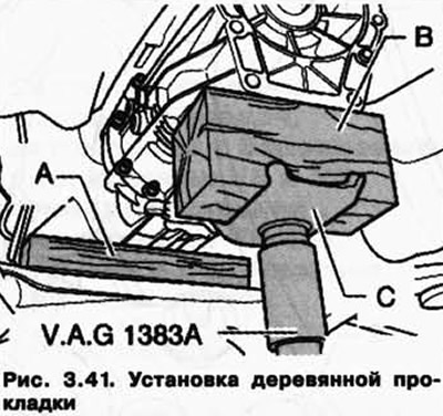
Install the engine and gearbox support VA G 1383 A under the gearbox.
Raise the gearbox just enough to remove the retaining device VW 785/ 1 V (used to remove and install the transfer case) from the gearbox.
Then place a piece of wood A about 50 mm thick between the gearbox and the subframe.
Make sure that the wooden gasket is not under the ATF pipes.
Lower and set aside the stand for the engine and gearbox VAG 1383 A.
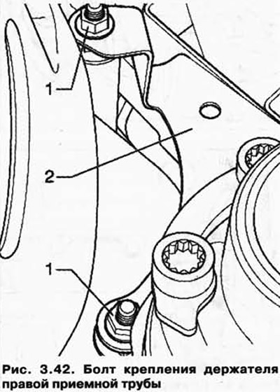
Unscrew the nuts 1 and remove the holder of the right exhaust pipe 2 from the starter mounting bolts (pic. 3.42).
The starter cable can be left installed.
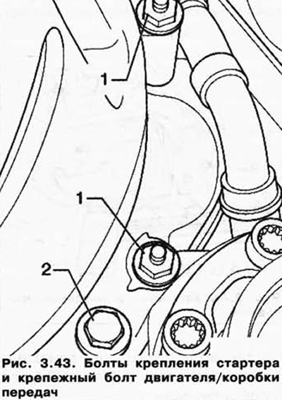
Unscrew bolts 1 and remove the starter from the engine/gearbox.
Remove the engine/gearbox mounting bolt 2 (pic. 3.43).
Unscrew the nut 2 of the tube holder of the cooling system from the bolt 3 (pic. 3.44).
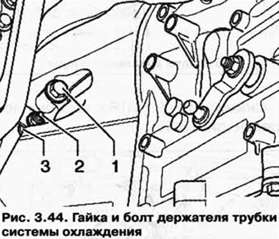
Unscrew the engine/gearbox connection bolts 1 and 3.
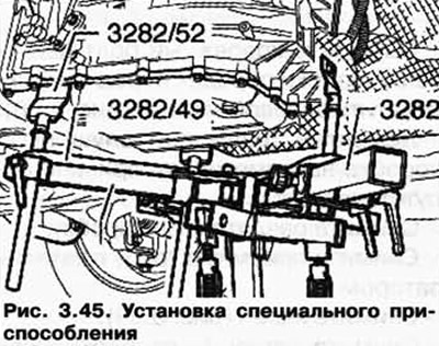
Adjust the position of the gearbox stop 3282 to dismantle the automatic gearbox «09D» using adjusting plate 3282/49.
Install the gearbox stop 3282 in the rack for the engine and gearbox VAG 1383 A.
Orient the arms of the gearbox stop levers in accordance with the holes in the adjusting plate.
The symbols on the adjusting plate show the necessary support parts, the arrow indicates the direction of travel.
Install the stand for the engine and gearbox VAG 1383 A with the gearbox stop 3282 under the car.
Fasten stop 3282/52 at the back of the gearbox with the M10x30 bolt (pic. 3.45).
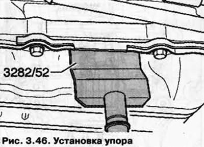
Fasten stop 3282/52 on the left and right of the gearbox under the oil sump (pic. 3.46).
Then lift the gearbox just enough to remove the wood spacer between the gearbox and the subframe.
When lowering, make sure that the ATF pipes are not pinched between the gearbox and the subframe.
Carefully lower the gearbox until the motor contacts the wood pad on the tandem pump and rests against the bulkhead.
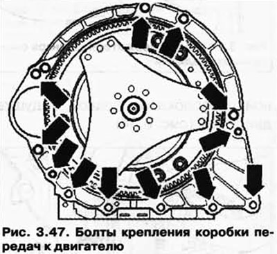
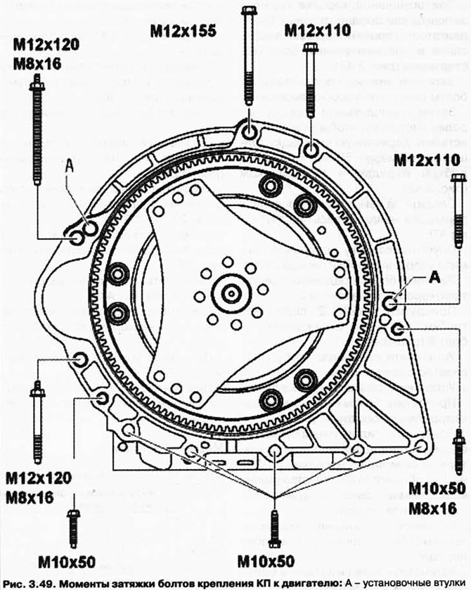
Overview of engine/gearbox connecting bolts.
Unscrew the two connecting bolts of the engine / gearbox at the top left (pic. 3.47).
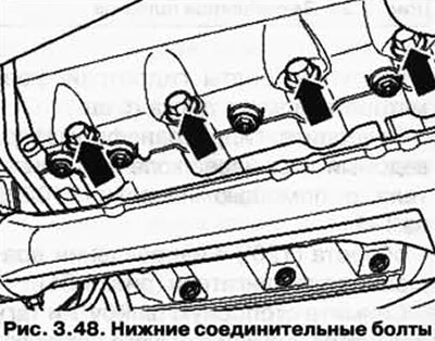
Remove the lower engine/gearbox connecting bolts (pic. 3.48).
Push the gearbox away from the engine (mounting sleeves). At the same time, squeeze the torque converter out of the driven disk from the ATF pump, do not turn the torque converter.
Mark the position of the torque converter in relation to the gearbox.
These marks are necessary during installation so that the holes of the mounting bolts in the torque converter and the driven disk match.
Then alternately pull the gearbox down and lower.
Secure the torque converter from falling out.
Installation
Installation is carried out in the reverse order. In doing so, the following must be taken into account.
If the ATF oil is contaminated or before installing a new transmission, clean the ATF cooler and ATF lines.
Clean the threads of bolts previously lubricated with thread varnish with a wire brush. Then install the bolts using AMV 185 101 A1 thread varnish.
All threaded holes into which self-locking bolts/screws are screwed must be cleaned with a tap to remove any residues of thread varnish. Otherwise, during the next dismantling, their threads may be torn off.
Always replace self-locking bolts and nuts.
Before installing a new gearbox, the radiator and ATF pipes must be cleaned.
Before installing the gearbox, make sure that the torque converter is correctly installed in the gearbox.
Before installation, check the correct fit of the mounting sleeves.
Make sure the fitted bushings are in the correct position between the engine and gearbox. The absence of fitted bushings leads to a misalignment of the engine and gearbox, therefore, to the destruction of the plain bearing and torque converter hub.
Align the marked marks on the gearbox and torque converter.
If there are no marks, turn the torque converter and driven plate towards each other so that the threaded hole in the torque converter and the hole in the driven plate are in the center of the starter mount.
With the gearbox lowered, tighten the two engine/gearbox connecting bolts at the top left and the connecting bolt under the starter (pic. 3.47).
Tighten the lower engine/gearbox connecting bolts.
Then raise the gearbox just enough to fit a piece of wood about 50mm thick between the gearbox and the subframe (pic. 3.48).
Make sure that the wooden gasket is not under the ATF pipes.
Lower the gearbox and remove the gearbox support 3282.
Tighten the engine/gearbox connection bolts 1 and 3.
Screw the nut 2 of the cooling system pipe holder onto the bolt 3 (pic. 3.44).
Install downpipe/catalyst with bracket.
Install the transfer box.
Tighten the torque converter/driven plate bolts (6 pcs.)
Turn the torque converter/driven plate through the engine crankshaft using the T10225 1/3 turn (120°) in the direction of rotation of the motor shaft (pic. 3.31).
Install starter.
Tighten the remaining engine/gearbox connecting bolts.
Install the screen and tighten the bolts with a torque of 10 Nm (pic. 3.39).
Install shield 1 and tighten the bolts to 10 Nm.
Connect plug connections 2-4 (pic. 3.40).
Tighten the ATF pipe holder bolt on the gearbox (pic. 3.37).
Remove the plugs and insert the ATF pipes all the way into the gearbox (pic. 3.36).
Tighten the bolt.
Install support 1.
Install bolts 2, lubricated with thread varnish, and tighten (pic. 3.35).
Press the selector rod 2 with your hand against the gear selector rod (rice. 3.11).
When installing, do not bend the shift shaft lever, otherwise it will not be possible to finely adjust the gear shift.
Install a new lock washer 1.
Tighten the coolant hose holder bolts on the right engine mount (pic. 3.33).
Install noise insulation holders 1 and 2 (pic. 3.32).
Unscrew the key T10225 from the crankshaft.
Replace seal cap.
Tighten the soundproofing holder bolts (pic. 3.30).
Tighten the bolts (3 pcs.) soundproofing.
Install the cooling system hoses 1-4 on the noise insulation (pic. 3.29).
Remove the wood gasket 1 and adhesive tape 2 from the tandem pump (pic. 3.28).
Be sure to follow the battery disconnection sequence.
Carry out work operations after connecting the battery.
Check selector lever adjustment, adjust if necessary.
Check the ATF level and add oil.
When checking the ATF level, check the ATF tube outlets for leaks (pic. 3.36).
Visitor comments