
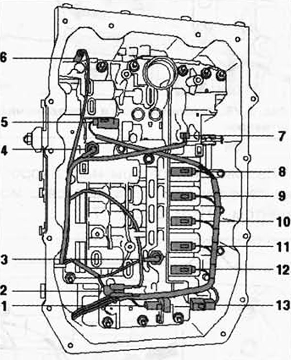
Pic. 3.74. Valve box components:
1 - solenoid valve 2; 2 - plug connection of gearbox output shaft speed sensor; 3 - pressure sensor for hydraulic system 2 in automatic transmission G194; 4 - pressure sensor for hydraulic system 1 in automatic transmission G193; 5 - solenoid valve 4; 6 - speed sensor of the gearbox output shaft; 7 - gearbox oil temperature sensor; 8 - solenoid valve 6; 9 - solenoid valve 3; 10 - solenoid valve 5; 11 - solenoid valve 10; 12 - solenoid valve 1/
The spool box and/or tubes can be removed/installed both with the gearbox installed and with it removed.
Removing
If this operation has not yet been completed, remove the oil pan and oil strainer.
Carefully disconnect the G1931 hydraulic pressure sensor 1 and the G1942 hydraulic pressure sensor 2 (rice. 3.73).
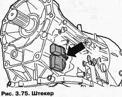
Unscrew the plugs (pic. 3.75).
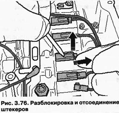
Carefully unlock the plugs and disconnect (pic. 3.76).
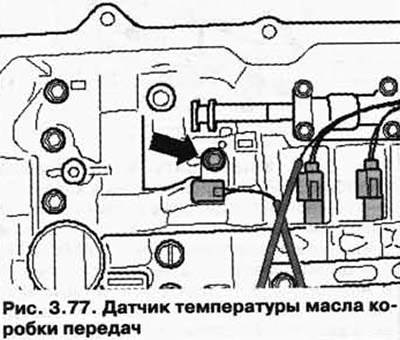
Gearbox oil temperature sender G93 is tightened to 10 Nm (pic. 3.77).
Loosen the spool bolts «criss-cross» (pic. 3.78).
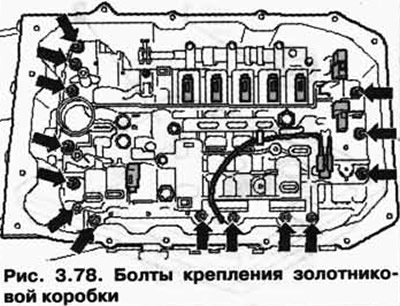
Tightening torque: 8 Nm +90°.
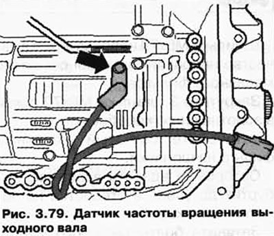
Gearbox output speed sender G195 is tightened to 10 Nm (pic. 3.79).
Installation is carried out in the reverse order.
After installation, fill in ATF, then check the ATF level, add oil if necessary.
Visitor comments