
Before removing the power unit, do the following:
- if an anti-theft system with a security code is installed on the car, then you must have the code with you in order to turn on the system after connecting the battery;
- when removing the engine, you will need to disconnect a large number of electrical wires, as well as vacuum and coolant hoses. Before removing wires and hoses, mark them with tags;
- before installation work in the engine compartment, it is necessary to cover the front fenders of the car with a dense cloth.
Remove the power unit in the following order:
- turn off the engine and remove the key from the ignition;
- disconnect the terminal «–» from AB;
Attention! In order to avoid damage to the computer, it is necessary to disconnect the battery terminals only when the ignition is off. Moreover, to completely turn off the ignition, you must wait at least 20 s and only after that you can turn off the terminal «–» from AB.
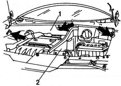
Pic. 18. AB removal: 1 - air duct casing; 2 - partition
- unscrew the screws (shown by arrows, fig. 18) and remove the casing 1 of the air duct and the partition 2;
- remove AB (see section 16.1);
- drain the coolant from the cooling system (see section 19.1);
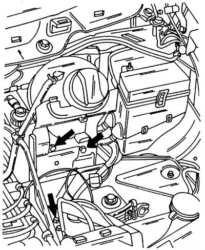
Pic. 19. Removing the battery cover
- unscrew the screws (shown by arrows, fig. 19), move to the side and remove the battery cover together with the expansion tank of the cooling system;
- remove the V-belt for driving engine units;
- disconnect the air line hose from the throttle body;
- using a spark plug wrench, remove the spark plugs and stack them in cylinder order. For the VR6 engine, the caps of the candles and the candles themselves can only be removed using a special spark plug wrench numbered 3277A;
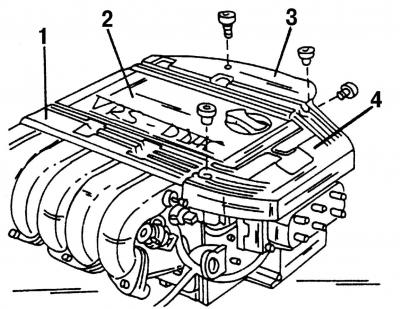
Pic. 20. Removing the center cover on the top of the intake manifold: 1, 3, 4 - high voltage wire guides; 2 - central cover
- remove guides 1, 3 and 4 (pic. 20) high voltage wires and remove the central cover 2 of the upper part of the intake manifold;
- remove the throttle cable together with its support, for which unscrew the support and remove the end of the cable. Do not pull out the clip holding the throttle cable in its support (as in this case it will be necessary to adjust the tension of the throttle cable);
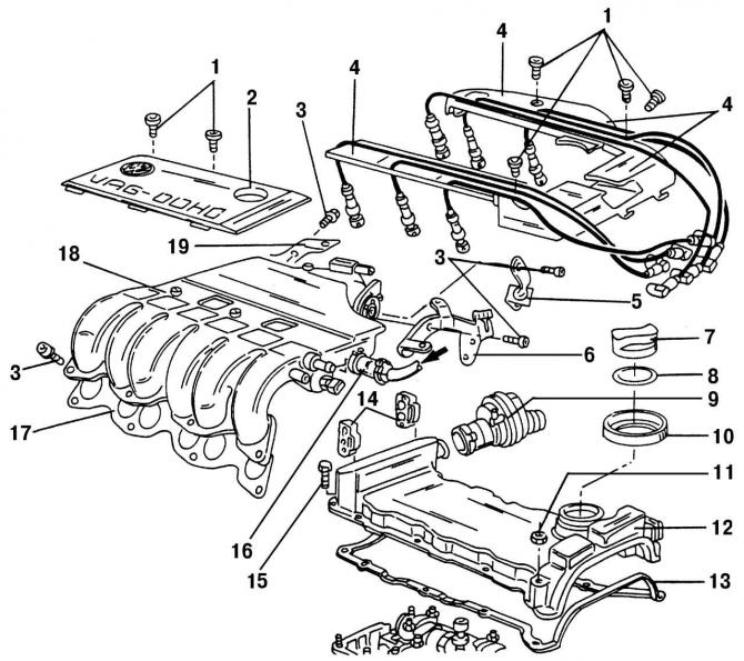
Pic. 26. Details of the upper part of the cylinder head: 1 - bolts (5 Nm); 2 - central cover (above the top of the intake manifold); 3 - bolts (25 Nm); 4 - spark plug wire holders; 5 - throttle cable holder; 6 - rear left bracket of the upper part of the inlet pipeline; 7 - filler cap for oil filling; 8 - sealing gasket; 9 - crankcase ventilation valve; 10 - ring in the cylinder head cover; 11 - nut (10 Nm); 12 - cylinder head cover; 13 - sealing gasket of the cylinder head cover; 14 - holders of fuel lines; 15 - bolt (10 Nm); 16 - vacuum hose; 17 - sealing gasket of the upper part of the intake manifold; 18 - the upper part of the intake manifold; 19 - rear right bracket of the upper part of the intake manifold
- disconnect the spring clips of the fuel line holders 14 (pic. 26) supply and removal of fuel;
- mark the fuel lines and disconnect the fuel inlet and outlet hoses from the fuel distributor;
Attention! The fuel lines are under pressure. Before disconnecting the fuel hose from its mount, grasp the fuel hose connection with a thick rag, and, carefully pulling it off the mount, relieve pressure in the system.
- disconnect the large 42-pin connector located near the ignition coil;
- disconnect the brake booster vacuum hose;
- Disconnect the power steering pipe from the fitting at the engine. Unscrew the power steering pump together with the bracket and hang it on a wire to the body. Do not twist the hoses and make sure that the pump does not hang on the hose;
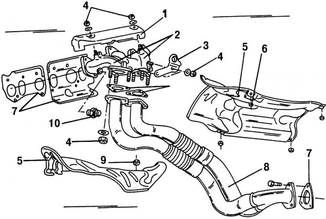
Pic. 100. Elements of the front of the exhaust system: 1 - engine thermal protection screen; 2 - exhaust manifold, consisting of two parts; 3 - lifting eye; 4 - nut, 40 Nm; 5 - engine thermal protection screen; 6 - nut of the engine thermal protection screen; 7 - gasket, for replacement; 8 - receiving pipe; 9 - nut, 10 Nm; 10 - fitting for connecting the EGR system, 35 Nm
- disconnect the downpipe 8 and the middle part of the exhaust system with the catalyst from the exhaust manifold 2 (pic. 100 and 101);
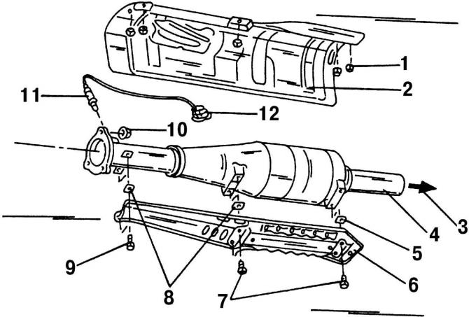
Pic. 101. Elements of the middle part of the exhaust system (located between the exhaust pipe and the catalyst muffler): 1 - nut of the thermal protection screen; 2 - thermal protection screen; 3 - direction to the first muffler; 4 - catalyst; 5 - protective collar; 6 - thermal protection screen; 7 - bolt, 10 Nm; 8 - protective collar; 9 - bolt, 10 Nm; 10 - nut, 40 Nm; 11 - lambda probe; 12 - black plug
- the VR6 engine has a secondary air supply system, the main parts of which are located near the radiator. To dismantle the engine, it is necessary to remove the casing with the fan and the secondary air pump motor (see subsection 5.2.2);
- disconnect all coolant hoses, vacuum hoses and engine ventilation hoses from the engine;
- Disconnect all electrical wires from the engine and transmission. Among them are wires: alternator, starter, hydraulic pressure oil switch, various sensors. Most connections are made using plug-in sockets;
- remove the generator;
if a manual transmission is installed:
- disconnect the hose from the clutch slave cylinder;
- remove the shift rod from the gearbox (see section 10.1);
- remove both drive shafts from the mountings in the gearbox (see section 11.1);
on a car with automatic transmission:
- remove the draft of the operating mode selection lever;
- remove both drive shafts from the mountings in the gearbox,
- if the car is equipped with air conditioning, then in addition to this section, be sure to read the relevant recommendations;
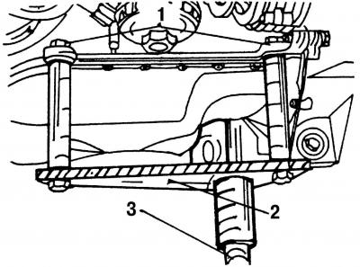
Pic. 21. Engine support: 1 - bolts; 2 - lifting yoke; 3 - lift
- support the engine from below. At the service station, a special device is used for this (pic. 21), under which the car jack is then substituted. In addition, you should insure the lift, which supports the engine from above by the hinges. If the car jack slips, the engine will then be held by the jack;
- remove the balancing (pendulum) suspension. It is connected to the front support, so you should read the corresponding section in order to learn more about its fastening;
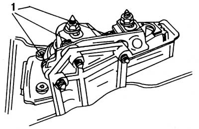
Pic. 22. Right engine mount: 1 - mounting bolts
- remove bolts 1 (pic. 22) fastenings of a support of the right suspension bracket of the engine. Please note that different tightening torques are used to tighten the engine mount bolts and nuts;
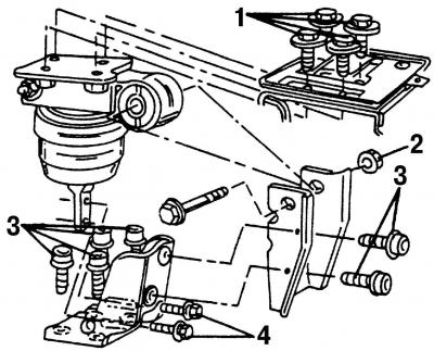
Pic. 23. Disassembled engine mount on a car with a manual transmission. Tightening torques for engine mount mounting bolts: 1 = 55 Nm; 2 = 110 Nm; 3 = 100 Nm; 4 = 20 Nm
- Turn out bolts of fastening of a support of the left suspension bracket of the engine. Fixture of a support of the left suspension bracket (pic. 23) engine depends on the type of gearbox installed. At this stage of work, it is necessary to unscrew only bolts 1, the location of which is the same for all types of gearbox;
- with a second person, slowly lower the power unit out of the engine compartment. Make sure that the engine does not damage the body.
Installing the power unit is carried out in the reverse order of removal, while doing the following:
- check the thickness of the clutch disc linings. In case of wear, replace the driven disk;
- carefully drive the power unit into the engine compartment. Be careful not to damage the parts and components of the car;
- when aligning the engine with the suspension mount fasteners, hand-tighten the mount bolts 5-6 turns by hand. Rock the engine back and forth (it shouldn't be energized);
- finally tighten the power unit mount bolts to the following torques:
- pos. 1 = 55 Nm; pos. 2 = 110 Nm; pos. 3 = 100 Nm; pos. 4 = 20 Nm (pic. 23) - for an engine with a manual transmission;
- pos. 1 = 55 Nm; pos. 2 = 60 Nm (pic. 24) – right engine mount;
- pos. 1 = 55 Nm; pos. 2 = 110 Nm; pos. 3 = 60 Nm (pic. 25) - right engine mount on a car with an automatic transmission;
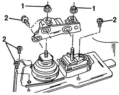
Pic. 24. Right engine mount disassembled. Tightening torques for suspension mounting bolts: 1 = 55 Nm; 2 = 60 Nm
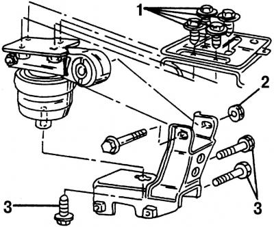
Pic. 25. Right engine mount disassembled on a car with an automatic transmission. Tightening torques for suspension mounting bolts: 1 = 55 Nm; 2 = 110 Nm; 3 = 60 Nm
- install a balancing (pendulum) suspension (see section 13);
- install drive shafts. Using a special wrench, tighten the multi-sided bolts to the specified tightening torque. For manual and automatic transmissions, the tightening torques are different (cm. «Torque table»);
- depending on the type of gearbox, install the rods and, if necessary, adjust the gearshift mechanism;
- connect the hose to the clutch slave cylinder and secure it with a spring clip (for manual transmission);
- Connect the downpipe with catalytic converter to the exhaust manifold. After aligning the muffler and exhaust pipe, hang them on the suspension rings. Make sure the installation is correct. The suspension rings must have uniform tension and must not be deformed;
- install the power steering pump;
- install a casing with a fan and a secondary air pump motor;
- install the V-belt for driving engine units;
- install the throttle cable and check its operation;
- install the intake air hose and air filter;
- install all previously disconnected electrical wires;
- Pour coolant into the cooling system with the heater valve open. Bring the coolant level in the expansion tank to the required level, tighten the cap of the expansion tank. Turn on the engine for a few minutes in order to release all the air pockets. Then check the coolant level in the expansion tank and add coolant if necessary;
- remove air from the hydraulic clutch release by pumping with the obligatory participation of an assistant;
- Plug in the battery and test drive. Check all hose connections for tightness;
- enter the anti-theft code (if it is installed on the car).
As soon as possible, you should call on the service station in order to check the memory of the fault recorder of the self-diagnosis system.
Visitor comments