
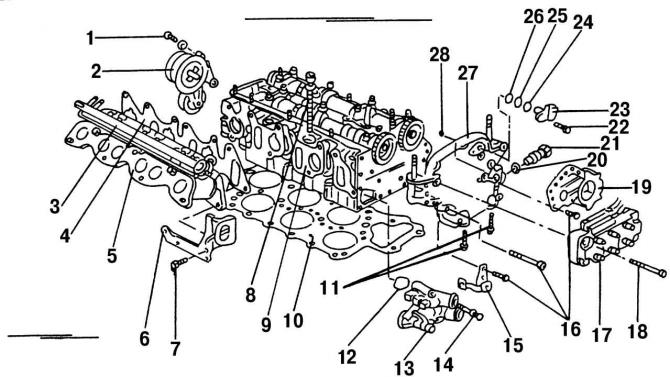
Pic. 28. Partially disassembled cylinder head (parts located on the top of the head were removed): 1 - bolt, 25 Nm; 2 - belt tensioner; 3 - fuel supply distributor; 4 - sealing gasket of the lower part of the intake manifold; 5 - the lower part of the intake manifold; 6 - lifting eye; 7 - bolt, 25 Nm; 8 - a bolt of fastening of a head of the block of cylinders; 9 - cylinder head; 10 - cylinder head gasket; 11 - bolt, 25 Nm; 12 - O-shaped sealing ring; 13 - thermostat housing; 14 - bolt, 10 Nm; 15 - cable holder; 16 - bolt, 10 Nm; 17 - ignition coil; 18 - bolts, 10 Nm; 19 - holder; 20 - sealing ring; 21 - chain tensioner, 30 Nm; 22 - bolt, 10 Nm; 23 - Hall sensor; 24 - spacer ring; 25 - O-ring; 26 - spacer ring; 27 - camshaft cover; 28 - O-ring
- remove all remaining parts located on the cylinder head (pic. 28);
- clamp the cylinder head with a clamp screwed to the inlet manifold set screw;
- remove the camshafts (this can be done on a non-removed engine), For what:
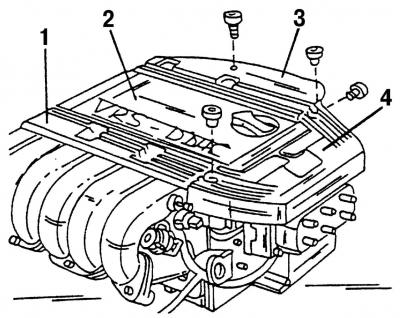
Pic. 27. The upper part of the intake manifold: 1, 3, 4 - high voltage wire guides; 2 - central cover
- remove the spark plug wire guides (pic. 27);
- remove the top part of the inlet pipeline. Cover the open inlets with a clean cloth to prevent foreign bodies from getting inside;
- rotate the crankshaft so that the piston of the first cylinder is at top dead center (TDC). If the engine is not removed, then you can slightly raise the front wheel, engage fifth gear and rotate the wheel to set the piston to TDC. If the engine is removed, then put a spanner wrench on the flywheel nut of the crankshaft and turn the shaft so that both camshaft lobes for the valves of the first cylinder look round side up;
- remove the ignition coil;
- if the engine is not removed, remove the cylinder head cover;
- remove the protective cover of the camshaft drive sprockets;
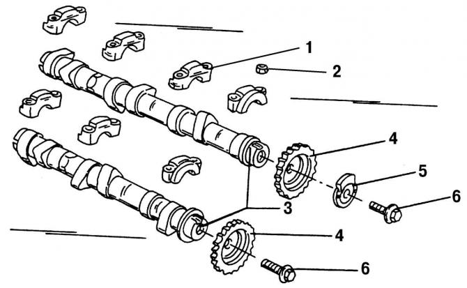
Pic. 31. Components of camshafts with bearing caps and sprockets: 1 - camshaft bearing cover; 2 - nut, 20 Nm; 3 - camshafts; 4 - camshaft sprockets; 5 - drive mechanism of the Hall sensor; 6 - bolts, 100 Nm
- remove bolts 6 (pic. 31) sprockets 4 camshaft drives;
Pic. 32. Fixing camshafts. The arrows show the hexagons designed to fix the camshafts
- fix the camshafts in a stationary position. To do this, each shaft has a hexagon (pic. 32, shown by an arrow), on which to put the open end wrench «by 24 mm» and hold the camshaft.
- unscrew the tensioner 21 (pic. 28) chains on the side of the cylinder head;
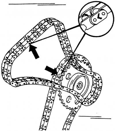
Pic. 33. Places for marking the camshaft drive chains before removal are shown by arrows
- remove the camshaft drive sprockets. If the camshaft drive chain has not yet been removed, note the direction of installation of the chain (pic. 33) so that it can be installed correctly;
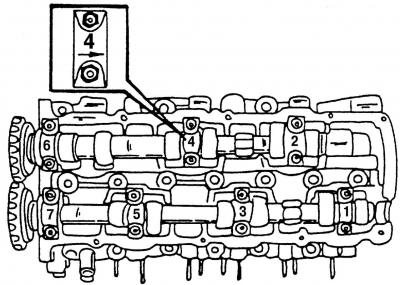
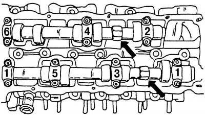
Pic. 34. Numbering of camshaft bearing caps. Each cover has an arrow showing the installation direction
- first remove the camshaft of cylinder bank 1, 3 and 5 (pic. 34). To do this, loosen both outer bearing caps (numbers 1 and 7), and then, having unscrewed them completely, remove the covers;
- to evenly unload the valve springs, alternately loosen the nuts of the bearing caps crosswise (number 3 and 5) so that the bearing caps are not under pressure from the springs;
- remove both bearing caps;
- remove the camshaft from the cylinder head bearings;
- remove the camshaft of cylinder number 2, 4 and 6 (pic. 34). To do this, alternately loosen the number 4 bearing cap nuts in a crosswise pattern and remove the bearing cap;
- similarly remove bearing caps number 2 and number 6;
- remove the second camshaft;
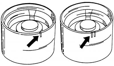
Pic. 35. Marking of hydraulic pushers
- put scratch marks on the inside of the pushers, i.e. the first pusher - one risk, the second pusher - 2 risks, etc. (pic. 35), since they should not be confused (start the countdown from the drive side of the engine units) and take out the pushers. Do not fold the pushers, but put the contact plane down;
Note. The tappets are equipped with hydraulic elements that regulate the gap in the valve actuator, and therefore the tappets must be handled with care.
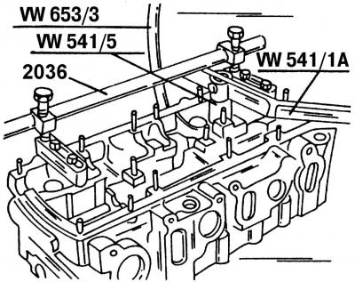
Pic. 36. Removing the valves using a special tool from the company «Volkswagen»
- the standard tool for removing and installing valves is tool number 2036 (pic. 36). It is attached to the cylinder head. Release valve 8 (pic. 37) from valve stem halves (crackers) 2, compressing springs 4 with fixture 2036;
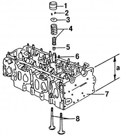
Pic. 37. Details of the valve drive mechanism: 1 - hydraulic pusher; 2 - valve stem halves (crackers); 3 - upper plate of the valve spring; 4 - valve springs; 5 - oil deflector cap; 6 - valve guide sleeve; 7 - cylinder head; 8 - valves; a - cylinder head height
- to remove the valves, you can also use a piece of pipe that is put on the upper spring plate. Under the valve plate on the other side, you need to put something to fix it. Tap the pipe briefly with a hammer until the valve stem halves come out. They will remain inside the pipe;
- take out the top plate 3 (pic. 37) with springs 4, turn the cylinder head 7 and remove the valve 8 from the underside;
- remove the oil deflector cap 5 from the guide sleeve 6;
Note. Always replace oil seals with new ones.
- if the car has a high mileage or work is carried out on a used car about which little is known, then before installing the cylinder block in place, measure the height of the cylinder head - the value a (pic. 37).
Visitor comments