



Below in the text there are also drawings of parts and assemblies, however the lists of parts and assemblies attached to them contain technological recommendations for repair.
Attention!
- When installing a new cylinder head, before mounting the camshaft housing, it is necessary to lubricate all contact surfaces between the support elements, roller levers and the camshaft bed with engine oil.
- The plastic spacers included in the repair kit for protecting open valves may only be removed immediately before installing the cylinder head.
- When replacing the cylinder head, you should also drain the old coolant and fill it with new coolant.
- All supporting and working surfaces must be lubricated with engine oil before installation work.
- Disassembly and assembly of the intake manifold.
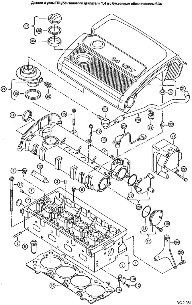
List of parts and assemblies of the cylinder head of a 1.4 L petrol engine with the letter designation BSA for figure VC 2.051
| Pos. | Part number according to the catalog | Name | Note | Pcs. |
| 1 | 036 103 351 F | Cylinder head | 1 | |
| 1A | 036 131 550 H | Pad | X | |
| 1B | 036 131 281 | Sealing plate | X | |
| 1C | N010 293 15 | Hex head screw | M8x16 | X |
| (1) | 036 103 264 BH | Cylinder head with valves | Spare parts supply option | 1 |
| 2 | N013 210 2 | Pin | 6 M6x16 | |
| 3 | N044 410 4 | Hairpin | M8x28 | 9 |
| 5 | N029 456 2 | Threaded plug | M16x1.5 | 1 |
| 6 | N029 456 2 | Threaded plug | M16x1.5 | 1 |
| 7 | N011 914 8 | Lid | A24 | 1 |
| 8 | 056 103 379 | Plug | 7,4 | 4 |
| (8) | 056 103 379 A | Plug | 8 | X |
| 10 | b036 103 383 AM | Cylinder head gasket (metal) | 1 | |
| 11 | 036 103 384 B | Cylinder head fastening screw with internal hexagon | M9x 1.25x138 | 10 |
| 12 | D 188 003 AI | Sealant | 100G POS.13 | X |
| (12) | D 154 102 AI | Sealant | 50G | X |
| 13 | 036 103 473 K | Cylinder head cover | 1 | |
| 14 | 036 103 085 A | Camshaft oil seal | 42x8 | 2 |
| 15 | N 10247503 | Cylinder head cover fastening screw with internal hexagon | M6x65 | 11 |
| 16 | N 103 008 03 | Allen bolt | M6x45 | 4 |
| 17 | 036 103 111 | Cylinder head cover end cap (outlet) | 1 | |
| 18 | N903 445 01 | Sealing ring | 45x3 | AND. |
| 19 | N100 829 07 | Hex head screw | M6X16.Z1 | 2 |
| 20 | 036 103 111 A | Cylinder head cover end cap (intake) | 1 | |
| 21 | High voltage transformer | 1 | ||
| 22 | High voltage transformer mounting screw | 3 | ||
| 23 | Pulse sensor | |||
| 24 | 036 115 302$ | Oil filler neck | 1 | |
| 25 | b06A 103 483 D | Oil filler neck gasket | 1 | |
| 26 | 036 103 638 A | Ventilation tube fitting seal | 1 | |
| 27 | 036 103 175 A | Valve | 1 | |
| 28 | 036 103 560 | Ventilation tube | 1 | |
| 29 | 036 103 733 B | Ventilation tube clamp | 1 | |
| 31 | Air filter | 1 | ||
| 32 | 036 129 689 B | Emphasis | 4 | |
| 33 | 036 129 846 | Expansion pin | 2 | |
| 34 | 036 103 388 E | Hinge, hanging | 1 | |
| 35 | N102 394 02 | Allen screw | M8x22 | 2 |
| 36 | 021 133 287 A | Oil filler cap sealing ring | 1 | |
| 37 | 06B 103 485 C | Oil filler cap | 1 | |
| 38 | b06A 104 83 D | Oil filler cap gasket | 1 |
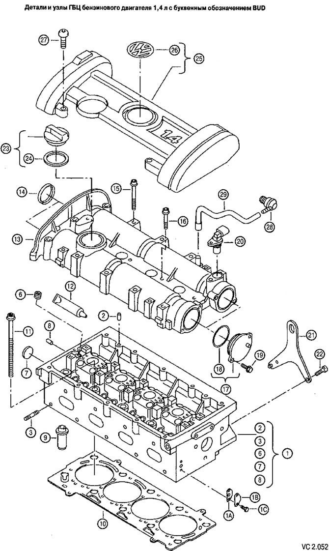
List of parts and assemblies of the cylinder head of a 1.4 L petrol engine with the letter designation BUD for figure VC2.052
| Pos. | Part number according to the catalog | Name | Note | Pcs. |
| 1 | 036 103 351 G | Cylinder head | 01029315 | 1 |
| 1A | 036 131 550 H | Pad | ||
| IB | 036 131 281 | Sealing plate | ||
| 1C | N010 293 15 | Hexagon head bolt | M8x16 | |
| 2 | N013 210 2 | Pin | 6M6x16 | 2 |
| 3 | N100 878 02 | Hairpin | M8Ax25 | 9 |
| b | N029 456 2 | Threaded plug | M1bx 1.5 | 1 |
| 7 | N011 914 8 | Lid | 24 | 1 |
| 8 | 056 103 379 | Plug | 7,4 | 4 |
| (8) | 056 103 379 A | Plug | 8 | |
| 10 | b036 103 383 AM | Cylinder head gasket (metal) | 1 | |
| 11 | 036 103 384 B | Hexagon socket head cap screw for G5C cover | N19x1,25x138 | 10 |
| 12 | D188 003 AI | Elastic sealant | 100G POS:13 | |
| (12) | D154 102 AI | Sealant | 50G | |
| 13 | 036 103 473 AM | Cylinder head cover | 1 | |
| 14 | P036 103 085 A | Shaft sealing ring | 42x8 | 2 |
| 15 | N102 475 04 | Allen bolt | AM6x65 | 11 |
| 16 | N103 008 05 | Allen bolt | M6x45 | 4 |
| 17 | 036 103 111 | Lid | 2 | |
| 18 | N903 445 01 | Sealing ring | 45x3 | 2 |
| 19 | N104 51405 | Flat head screw | M6x16-SN | 4 |
| 20 | Pulse sensor | 1 | ||
| 21 | 036 103 388 E | Sling loop | 1 | |
| 22 | N102 394 02 | Allen bolt | M8x22 | 2 |
| 23 | 06B 103 485 C | Lid | 1 | |
| 24 | b06A 103 483 D | Pad | 1 | |
| 25 | 036 103 925 CC | Casing | VW1.4 | 1 |
| 26 | 06F 103 940 | VW emblem | 1 | |
| 27 | N910 991 01 | Hexagon socket head cap screw | M6X20 | 4 |
| 28 | 030 103 175 B | Valve | 1 | |
| 29 | 03C 103 560 F | Air bleed hose | 1 |
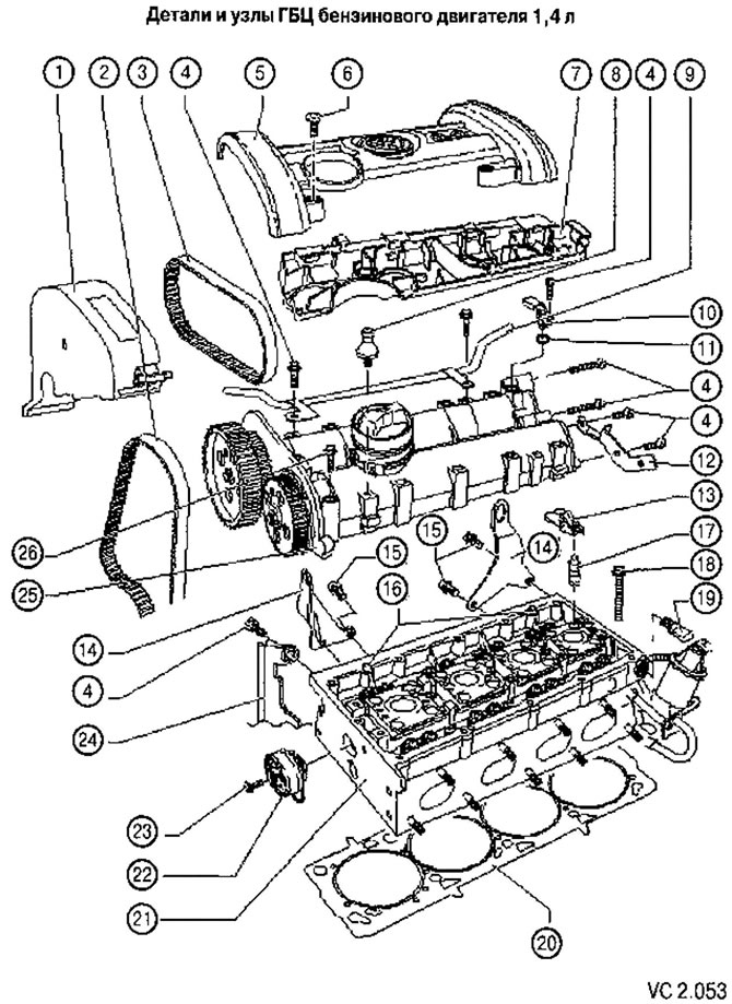
List of cylinder head parts and assemblies with notes on disassembly and assembly to figure VC 2.053:
1. Upper part of the timing belt guard.
2. Main drive toothed belt:
- Before removing, mark the direction of travel;
- check for wear;
- avoid fractures.
3. Toothed belt of the coupled drive:
- Before removing, mark the direction of travel;
- check for wear;
- avoid fractures.
4. Screw: 10 Nm.
5. Camshaft housing cover:
- only with engine letter designation BUD.
6. Cylinder head cover fastening screw: 10 Nm.
7. Casing of pipelines and wiring:
- tighten to the camshaft housing with a torque of 8 Nm.
8. Expansion screw: 6 Nm.
- for the air filter housing;
- only with the engine letter designation BSA.
9. Cooling system pipe.
10. Camshaft position sensor (hall effect) (G40).
11. Sealing ring:
- replace with a new one during assembly.
12. Bracket.
13. Rocker arm:
- check for jamming;
- lubricate the working surface;
- when installing, secure it to the support with a locking bracket.
14. Hanging eye.
15. Screw for fastening the lifting eye: 20 Nm.
16. Mounting pins.
17. Roller lever support with hydraulic clearance compensator:
- do not swap the supports;
- lubricate the working surface;
- Before installation, check the axial run-out of the camshaft.
18. Cylinder head bolt:
- replace with a new one during assembly.
19. Oil pressure sensor: 0.03 MPa (0.3 bar) (F1), 25 Nm.
20. Metal cylinder head gasket:
- replace with a new one during assembly;
- after replacement, change the coolant.
21. Cylinder head:
- check for deformation;
- there should be no oil or grease on the surfaces adjacent to the camshaft housing;
- if replaced, change the coolant.
22. Tension roller of the mating belt drive.
23. Tension roller mounting screw: 20 Nm.
24. Rear part of the timing belt cover.
25. Camshaft housing:
- remove any remaining old sealant;
- carefully clean the seating surfaces; they should be free of oil and grease;
- apply sealant before installation;
- when installing, install it vertically from above on studs and mounting pins
26. Camshaft housing mounting screws: 10 Nm + tighten by 1/4 turn (90°);
- replace with new ones during assembly;
- tighten from the center to the edges.
[The article is posted on the portal www.VWMANUAL.ru]
Visitor comments