



The fuel and exhaust system of car Volkswagen LT 28/35

Fuel system, exhaust system and emission control specifications
For information on modifications and latest models, see. in the Appendix at the end of this Guide. Specifications System type With electric fuel pump (mechanical on the very first...
For information on modifications and latest models, see. in the Appendix at the end of this Guide. Specifications System type With electric fuel pump (mechanical on the very first...

Air Cleaner — maintenance, removal and installation
1. With the frequency specified in the section " Routine maintenance " at the beginning of this Guide, you should do the following: remove the engine cover and unscrew the nut on...
1. With the frequency specified in the section " Routine maintenance " at the beginning of this Guide, you should do the following: remove the engine cover and unscrew the nut on...

Fuel filter — replacement
1. To replace the filter, disconnect the hoses from it, remove the old filter and install the new one. Keep an eye on that. so that the arrow on the filter matches the direction...
1. To replace the filter, disconnect the hoses from it, remove the old filter and install the new one. Keep an eye on that. so that the arrow on the filter matches the direction...
Fuel pump (mechanical) — removal and installation
1. Disconnect the hoses from the pump and plug them. 2. Unscrew the bolts and remove the pump, which is located on the left side of the cylinder head. 3. Pull out the pump rod,...
1. Disconnect the hoses from the pump and plug them. 2. Unscrew the bolts and remove the pump, which is located on the left side of the cylinder head. 3. Pull out the pump rod,...

Fuel pump (electric) — removal and installation
Models with chassis number up to 288 2506 977 1. Disconnect the negative cable from the battery. 2. Disconnect the electrical wiring from the pump. 3. Remember the location of the...
Models with chassis number up to 288 2506 977 1. Disconnect the negative cable from the battery. 2. Disconnect the electrical wiring from the pump. 3. Remember the location of the...

Fuel level sensor — removal and installation
If both the fuel gauge and coolant temperature gauge are giving incorrect readings, the cause may be a faulty voltage regulator (for more details, see. in chapters 2 and 10 ). 1....
If both the fuel gauge and coolant temperature gauge are giving incorrect readings, the cause may be a faulty voltage regulator (for more details, see. in chapters 2 and 10 ). 1....

Fuel tank — removal, cleaning and installation
1. Disconnect the negative cable from the battery. 2. On models with a cargo platform, remove the spare tire, unscrew the bolts securing the wheel carrier, and move the latter to...
1. Disconnect the negative cable from the battery. 2. On models with a cargo platform, remove the spare tire, unscrew the bolts securing the wheel carrier, and move the latter to...
Carburetor — regulation of idle speed and mixture composition
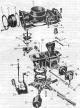
1. The quality screw on the carburetors in question is sealed after factory adjustment of the mixture composition. Typically, idle speed is adjusted by turning the idle speed...
1. The quality screw on the carburetors in question is sealed after factory adjustment of the mixture composition. Typically, idle speed is adjusted by turning the idle speed...

Carburetor — removal and installation
1. Remove the engine cover. 2. Disconnect the air intake duct from the air cleaner from the carburetor. 3. Disconnect the wires from the automatic choke unit and the air cut-off...
1. Remove the engine cover. 2. Disconnect the air intake duct from the air cleaner from the carburetor. 3. Disconnect the wires from the automatic choke unit and the air cut-off...
Carburetor — disassembly and assembly
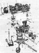
Figure 3.5. Disassembled carburetor: 1 - Retainer; 2 - Choke housing cover; 3 - Gasket; 4 - Top cover; 5 - Washer; 6 - Float chamber needle valve; 7 - Float axis spring; 8 - Float...
Figure 3.5. Disassembled carburetor: 1 - Retainer; 2 - Choke housing cover; 3 - Gasket; 4 - Top cover; 5 - Washer; 6 - Float chamber needle valve; 7 - Float axis spring; 8 - Float...

Carburetor — adjustment
1. The procedures described below are usually only necessary after a carburetor overhaul that results in a failure of the main adjustment. Automatic choke 2. Tighten the screws of...
1. The procedures described below are usually only necessary after a carburetor overhaul that results in a failure of the main adjustment. Automatic choke 2. Tighten the screws of...

Throttle Pedal Cable — adjustment
1. When the gas pedal is fully depressed, the gap between the throttle lever and the stop in the carburetor should be 1.0-1.5 mm (see figure 3.14). Figure 3.14. Clearance between...
1. When the gas pedal is fully depressed, the gap between the throttle lever and the stop in the carburetor should be 1.0-1.5 mm (see figure 3.14). Figure 3.14. Clearance between...

Exhaust Gas Afterburning System — description and maintenance
1. The exhaust gas afterburning system is essentially an air injection system in which fresh air is sucked into the intake manifold and then passes through passages in the...
1. The exhaust gas afterburning system is essentially an air injection system in which fresh air is sucked into the intake manifold and then passes through passages in the...

Manifolds and exhaust system — general information
1. The intake manifold is bolted to the left side of the cylinder head. 2. Before removing the intake manifold, it is necessary to disconnect the throttle cable, electrical wiring...
1. The intake manifold is bolted to the left side of the cylinder head. 2. Before removing the intake manifold, it is necessary to disconnect the throttle cable, electrical wiring...
Fuel system — troubleshooting
Note: Excessive fuel consumption and poor engine performance are not necessarily the result of a faulty fuel system or carburetor. Before attempting to diagnose a fault using the...
Note: Excessive fuel consumption and poor engine performance are not necessarily the result of a faulty fuel system or carburetor. Before attempting to diagnose a fault using the...
Fuel system specification — 2.4l engine
Power supply system - 2.4 L engine Carburetor Solex 1B1 Type Single-chamber carburetor with downdraft and manual choke Jets and basic installation data: Diffuser 28 Main jet x 135...
Power supply system - 2.4 L engine Carburetor Solex 1B1 Type Single-chamber carburetor with downdraft and manual choke Jets and basic installation data: Diffuser 28 Main jet x 135...

General description — models with a 2.0l engine produced since 1980.
1. Since the early 1980s, all LT models with a 2.0L engine have been equipped with Solex 1B1 carburetors. 2. This carburetor is a single barrel, downdraft, manual choke...
1. Since the early 1980s, all LT models with a 2.0L engine have been equipped with Solex 1B1 carburetors. 2. This carburetor is a single barrel, downdraft, manual choke...

Manual choke unit — removal, installation and adjustment (models with a 2.0 l engine produced since 1980)
4. Disconnect the choke control cable from the carburetor. 5. Loosen the choke block cover screws and remove the cover. 6. When replacing the cover, check that the bimetallic...
4. Disconnect the choke control cable from the carburetor. 5. Loosen the choke block cover screws and remove the cover. 6. When replacing the cover, check that the bimetallic...

Idle speed and mixture control (2.0L engine models produced since 1980)
Idle speed 9. Connect the tachometer to the engine in accordance with the manufacturer's instructions. 10. The engine must be at normal operating temperature. 11. All electrical...
Idle speed 9. Connect the tachometer to the engine in accordance with the manufacturer's instructions. 10. The engine must be at normal operating temperature. 11. All electrical...

Air damper starting clearance — adjustment (models with 2.0l engine produced since 1980)
34. Check the operation of the air damper lowering unit. 35. Pull the air damper cable out so that the serrated disc is facing its highest protrusion. 36. Loosen the choke block...
34. Check the operation of the air damper lowering unit. 35. Pull the air damper cable out so that the serrated disc is facing its highest protrusion. 36. Loosen the choke block...

Accelerator pump — regulation (models with 2.0l engine produced since 1980)
41. The procedure for checking the pump flow is the same as described in chapter 3, Section 11 , except for the following differences. 42. Set the air damper control lever to the...
41. The procedure for checking the pump flow is the same as described in chapter 3, Section 11 , except for the following differences. 42. Set the air damper control lever to the...

Choke cable (manual choke models) — general operating principles and adjustment
General principles of operation 46. Although the choke is manual in the sense that the air damper is opened and closed manually via a cable, it nevertheless has some elements of...
General principles of operation 46. Although the choke is manual in the sense that the air damper is opened and closed manually via a cable, it nevertheless has some elements of...

Throttle Damper and Timing Valve — checking and adjusting
58. The engine must be at normal operating temperature. 59. Start the engine and let it idle. 60. Press the control lever against the stop, moving it towards the vacuum block. 61....
58. The engine must be at normal operating temperature. 59. Start the engine and let it idle. 60. Press the control lever against the stop, moving it towards the vacuum block. 61....

Modified mixture enrichment valve (since November 1980)
65. Beginning in November 1980, a modified mixture enrichment valve began to be used on 1B1 carburetors. 66. Figure 14.32 shows two valves. The new type of valve has a flange on...
65. Beginning in November 1980, a modified mixture enrichment valve began to be used on 1B1 carburetors. 66. Figure 14.32 shows two valves. The new type of valve has a flange on...
General description — models with a 2.4 l engine
1. The fuel system on LT models with a 2.4L 6-cylinder engine, introduced in 1983, is basically the same as on models with a 2.0L 4-cylinder engine. 2. The fuel pump, fuel tank,...
1. The fuel system on LT models with a 2.4L 6-cylinder engine, introduced in 1983, is basically the same as on models with a 2.0L 4-cylinder engine. 2. The fuel pump, fuel tank,...

Air Filter — removal and installation (2.4l engine models)
4. Remove the cover located behind the driver's seat (see photo). Photos 6B.4. Removing the cover behind the front seat. 5. Loosen the clamps on the air cleaner cover and remove...
4. Remove the cover located behind the driver's seat (see photo). Photos 6B.4. Removing the cover behind the front seat. 5. Loosen the clamps on the air cleaner cover and remove...

Carburetor adjustment (models with 2.4L engine)
8. Regulation of idle speed and mixture composition is discussed in chapter 3, Section 8 . Please take the following features into account 9. By turning the adjusting screws in,...
8. Regulation of idle speed and mixture composition is discussed in chapter 3, Section 8 . Please take the following features into account 9. By turning the adjusting screws in,...

Carburetor — removal, overhaul and installation (models with a 2.4 l engine)
12. Perform the procedures described in chapter 3, Section 9 . 13. Remember that you are dealing with 2 fuel lines, the downstream and the downstream (see photo). Photo 6B.13....
12. Perform the procedures described in chapter 3, Section 9 . 13. Remember that you are dealing with 2 fuel lines, the downstream and the downstream (see photo). Photo 6B.13....

Fast Idle — checking and adjusting (2.4l engine models)
17. The engine must be at normal operating temperature. 18. The ignition timing and idle speed must be adjusted correctly. 19. Open the throttle valve and turn the choke cam so...
17. The engine must be at normal operating temperature. 18. The ignition timing and idle speed must be adjusted correctly. 19. Open the throttle valve and turn the choke cam so...

Carburetor Installation Procedures and Adjustments (2.4L Engine Models)
Note: You will need a hand vacuum pump and a vacuum gauge to perform the following procedures. If you do not have the necessary equipment, you should entrust this work to a...
Note: You will need a hand vacuum pump and a vacuum gauge to perform the following procedures. If you do not have the necessary equipment, you should entrust this work to a...

Intake manifold heating (models with 2.4L engine)
General description 58. The heater is installed on the lower surface of the intake manifold (see photo). Photo 6B.58. Intake manifold heater. 59. The heater consists of an...
General description 58. The heater is installed on the lower surface of the intake manifold (see photo). Photo 6B.58. Intake manifold heater. 59. The heater consists of an...

Hot air supply system (models with 2.4L engine)
65. The intake manifold heater also includes a hot air supply system that supplies hot air into the air intake at temperatures below 17°C. 66. The system's control valve is...
65. The intake manifold heater also includes a hot air supply system that supplies hot air into the air intake at temperatures below 17°C. 66. The system's control valve is...

Manifolds and exhaust system (models with 2.4L engine)
Collectors 79. The intake manifold is made as a single casting and is attached to the cylinder head using bolts with a hole in the head for a hexagon. 80. The carburetor is bolted...
Collectors 79. The intake manifold is made as a single casting and is attached to the cylinder head using bolts with a hole in the head for a hexagon. 80. The carburetor is bolted...

Fuel tank filler pipe installation (models with 2.4L engine)
87. Fuel tank filler pipes may vary depending on the body type. 88. When installing the filler pipe on the fuel tank, check that it is the correct type. 89. To ensure proper...
87. Fuel tank filler pipes may vary depending on the body type. 88. When installing the filler pipe on the fuel tank, check that it is the correct type. 89. To ensure proper...
This section is available on russian, bulgarian, belarusian, ukrainian, serbian, croatian, romanian, polish, slovak, hungarian
Similar sections from other manuals for VW cars:
Diesel engine: Power and control system Volkswagen Passat B4 (1988-1996)
Petrol engines 1.3 l: Supply system Volkswagen Golf 2 (1984-1993)
Power unit: Supply system Volkswagen Polo 4 (2001-2009)
Power unit: Fuel supply system Volkswagen Touareg 1 (2002-2006)
Diesel engines: Supply system Volkswagen Sharan 1 (1995-2000)
Power unit: Fuel system (diesel) Volkswagen Transporter T4 (1990-2003)
Diesel engine: Power and control system Volkswagen Passat B4 (1988-1996)
Petrol engines 1.3 l: Supply system Volkswagen Golf 2 (1984-1993)
Power unit: Supply system Volkswagen Polo 4 (2001-2009)
Power unit: Fuel supply system Volkswagen Touareg 1 (2002-2006)
Diesel engines: Supply system Volkswagen Sharan 1 (1995-2000)
Power unit: Fuel system (diesel) Volkswagen Transporter T4 (1990-2003)
Caddy 3
Beetle
LT 2D
LT 28
- General information
- User manual
- Daily care
- Maintenance
- Petrol engines 1.4 l
- Engine repair
- Cooling and lubrication system
- Power and exhaust system
- Petrol engines 1.6 l
- Engine repair
- Cooling and lubrication system
- Power and exhaust system
- Diesel engines
- Engine repair
- Cooling and lubrication system
- Power and exhaust system
- Transmission
- Mechanical gearbox 0AH
- Mechanical gearbox 0A4
- Drive shafts
- Chassis
- Car suspension
- Steering
- Brake system
- Body and wiring diagrams
- Interior and exterior
- Electrical circuits
- General information
- Maintenance
- Power unit
- Engine repair
- Cooling and lubrication system
- Supply system
- Exhaust system
- Transmission
- Clutch
- Car gearbox
- Chassis
- Front suspension
- Rear suspension
- Steering
- Brake system
- Wheels and tires
- Body
- Exterior
- Electrical equipment
- Equipment and devices
- Power devices
- Electrical circuits
- General information
- User manual
- Maintenance
- Power unit
- Petrol engines 2.3 l
- Diesel engines 2.5 l
- Diesel engines 2.8 l
- Injection system (diesel 2.8 l)
- Transmission
- Clutch
- Manual gearbox
- Differential
- Chassis
- Car suspension
- Steering system
- Brake system
- Body
- Body elements
- Heating system
- Electrical equipment
- Equipment and devices
- Electrical circuits
- General information
- Maintenance
- Power unit
- Petrol engines 2.0L
- Petrol engines 2.4L
- Diesel engines
- Cooling and heating
- Fuel and exhaust system
- Ignition system
- Transmission
- Clutch
- Car gearbox
- Cardan shaft
- Rear axle
- Chassis
- Brake system
- Car suspension
- Steering system
- Body
- Body elements
- Doors, locks and windows
- Electrical equipment
- Power devices
- Equipment and devices
- Electrical circuits