
English Русский
Български
Беларускі
Український
Српски
Hrvatski
Română
Polski
Slovenský
Magyar
  |  Articles  |  Sitemap  |  Contacts  |    |
Car maintenance Ford Car maintenance Hyundai Car maintenance Chevrolet Car maintenance BMW Car maintenance Audi Car maintenance Opel Car maintenance AvtoVAZ
VWmanual.ru


Main   Passat   Golf   Polo   Touareg   Tiguan   Sharan   Transporter   Others  
LT 28 (1975-1991) LT 2D (1996-2003) Beetle (1960-1986) Caddy 3 (2003-2010)

Carburetor Installation Procedures and Adjustments (2.4L Engine Models) (VW Lt 28)

  • Main
  • Volkswagen
  • LT 28
  • Power unit
  • Fuel and exhaust system
  • Carburetor Installation Procedures and Adjustments (2.4L Engine Models)
            0


Contents: Automatic choke ↓ Air damper lowering block ↓ Air damper starting clearance ↓ Vacuum unit - leak test ↓ Vacuum unit - checking operation ↓ Accelerator pump ↓ Starting clearance of the throttle…↓
Note: You will need a hand vacuum pump and a vacuum gauge to perform the following procedures. If you do not have the necessary equipment, you should entrust this work to a specialist.


Automatic choke


24. The alignment marks on the cover and the choke unit body must be aligned (see photo).
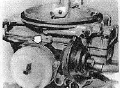
Photo 6B.24. Automatic choke cover alignment marks (shown by arrow) (2B6 carburetor).

Photo 6B.24. Automatic choke cover alignment marks (shown by arrow) (2B6 carburetor).


The original information is posted on the website vwmanual.ru

25. If necessary, loosen the cover screws, turn it so that the marks align, and tighten the screws again.

Air damper lowering block


23. Remove the air intake elbow.

27. Set the fast idle adjusting screw to the highest cam shoulder.

28. Start the engine without touching the gas pedal.

29. Close the air damper manually.

30. If the air damper release is working properly, it should close easily until a gap of approximately 4 mm is reached. After this, resistance should begin to be felt, which will increase as the air damper closes further.


31. If the air damper closes completely without resistance, the damper lowering unit should be checked.

32. Disconnect the block vacuum hose from the carburetor and connect a vacuum pump to it.

33. Create a vacuum and check that it is maintained in the block for 2 minutes.

34. If this is not the case, the air damper lowering unit should be replaced.

Air damper starting clearance


35. Remove the air intake elbow.

36. Remove the choke block cover

37. Press the gas pedal and set the adjusting screw (B) to the highest cam ledge (A) (see Figure 13.38).
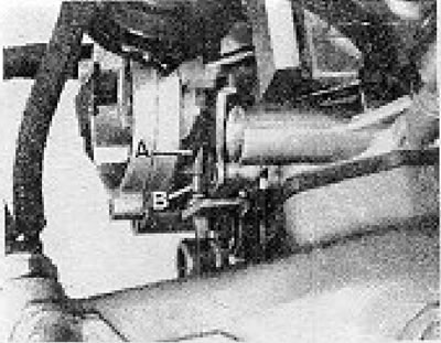
Figure 13.38. Checking and adjusting the air damper starting gap (2B6 carburetor) (Section 6B): A -…

Figure 13.38. Checking and adjusting the air damper starting gap (2B6 carburetor) (Section 6B): A - Cam; B - Adjusting screw.


38. Using an elastic band, lightly secure the air damper control lever.

39. Connect the vacuum pump to the air damper lowering unit.

40. Create a vacuum in the block.

41. Lightly press the air damper shaft with your finger to remove any play, and check the gap between the edge of the air damper and the carburetor wall, as indicated above.

42. If necessary, adjust the gap using the screw (B) (see Figure 13.39).
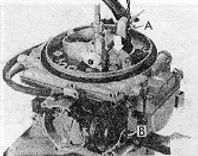
Figure 13.39. Dash of the air damper starting gap (2B6 carburetor) (Section 6B): A - Drill; B -…

Figure 13.39. Dash of the air damper starting gap (2B6 carburetor) (Section 6B): A - Drill; B - Adjusting screw.


Vacuum unit - leak test


43. Disconnect the vacuum hose from the carburetor and connect a vacuum pump to the hose.

44. Create a vacuum in the block and check that it is maintained for at least 2 minutes.

45. If the vacuum dissipates earlier, the vacuum block should be replaced.

Vacuum unit - checking operation


46. If the block leak test yielded positive results, a vacuum should be created in the block again.

47. Fully open the throttle valve of chamber 1. The throttle valve of chamber 2 must be opened by the vacuum block rod (see photo).
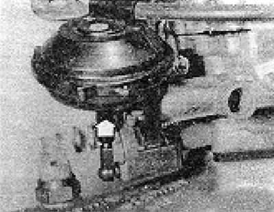
Photo 6B.47. Vacuum block rod - 2B6 carburetor (the arrow shows the direction of movement of the…

Photo 6B.47. Vacuum block rod - 2B6 carburetor (the arrow shows the direction of movement of the rod during testing).


48. Replace the vacuum unit if it does not open the throttle valve of chamber 2.

Accelerator pump


49. The accelerator pump flow can only be accurately determined using a special tester and therefore this work should be entrusted to a specialist.

Starting clearance of the throttle valve chamber 2


50. The throttle stop screw has a factory adjustment and under normal conditions it is best not to touch it. If you disassembled the throttle valve assembly or replaced the gasket during the carburetor overhaul, the throttle valve of chamber 2 can be adjusted as follows.

51. The adjusting screw is located under a protective plug, which must be replaced with a new one after adjustment is completed.

52. Remove the protective plug. Open the choke fully and close the throttle valve.

53. Loosen the screw (A) so that a gap is formed between it and the throttle lever (see Figure 13.40).
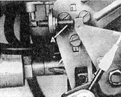
Figure 13.40. Adjusting the throttle valve of chamber 2 (2B6 carburetor) (Section 6B): A -…

Figure 13.40. Adjusting the throttle valve of chamber 2 (2B6 carburetor) (Section 6B): A - Adjusting screw.


54. Quickly open and close the throttle valve.

55. Turn the screw in until it just touches the throttle lever. To determine this moment, you can leave a thin sheet of paper between the screw and the lever and carefully move it to catch the moment when it is seized by the screw.

56. From this position, turn the screw another 1/4 turn.

57. Adjust idle speed and CO content in exhaust gases.

This article is available at russian, bulgarian, belarusian, ukrainian, serbian, croatian, romanian, polish, slovak, hungarian
The text has been checked: Kolesnikov Artem

Share information:

Previous articles
Fast Idle — checking and adjusting (2.4l engine models)
Carburetor — removal, overhaul and installation (models with a 2.4 l engine)
Carburetor adjustment (models with 2.4L engine)
Air Filter — removal and installation (2.4l engine models)
General description — models with a 2.4 l engine
Modified mixture enrichment valve (since November 1980)
Next articles
Intake manifold heating (models with 2.4L engine)
Hot air supply system (models with 2.4L engine)
Manifolds and exhaust system (models with 2.4L engine)
Fuel tank filler pipe installation (models with 2.4L engine)


Similar articles from other manuals for VW cars:
Starting the car engine Passat B3 (1988-1993)
Engine speed control — PICT carburetor with automatic choke Golf 2 (1984-1993, petrol)
Starting the engine from an auxiliary battery Polo 3 (1995-2003)
Car engine number Touareg 1 (2002-2006)
Car engine number Tiguan 1 (2007-2015)
Checking the engine oil level and replacing it Sharan 1 (1995-2000)
Starting the engine from another source Transporter T4 (1990-2003)
Link to this page in different formats


Visitor comments


No comments yet


How much will 45 + 45 =


Caddy 3 
  • General information
  • User manual
  • Daily care
  • Maintenance
  • Petrol engines 1.4 l
  • Engine repair
  • Cooling and lubrication system
  • Power and exhaust system
  • Petrol engines 1.6 l
  • Engine repair
  • Cooling and lubrication system
  • Power and exhaust system
  • Diesel engines
  • Engine repair
  • Cooling and lubrication system
  • Power and exhaust system
  • Transmission
  • Mechanical gearbox 0AH
  • Mechanical gearbox 0A4
  • Drive shafts
  • Chassis
  • Car suspension
  • Steering
  • Brake system
  • Body and wiring diagrams
  • Interior and exterior
  • Electrical circuits
Beetle 
  • General information
  • Maintenance
  • Power unit
  • Engine repair
  • Cooling and lubrication system
  • Supply system
  • Exhaust system
  • Transmission
  • Clutch
  • Car gearbox
  • Chassis
  • Front suspension
  • Rear suspension
  • Steering
  • Brake system
  • Wheels and tires
  • Body
  • Exterior
  • Electrical equipment
  • Equipment and devices
  • Power devices
  • Electrical circuits
LT 2D 
  • General information
  • User manual
  • Maintenance
  • Power unit
  • Petrol engines 2.3 l
  • Diesel engines 2.5 l
  • Diesel engines 2.8 l
  • Injection system (diesel 2.8 l)
  • Transmission
  • Clutch
  • Manual gearbox
  • Differential
  • Chassis
  • Car suspension
  • Steering system
  • Brake system
  • Body
  • Body elements
  • Heating system
  • Electrical equipment
  • Equipment and devices
  • Electrical circuits
LT 28 
  • General information
  • Maintenance
  • Power unit
  • Petrol engines 2.0L
  • Petrol engines 2.4L
  • Diesel engines
  • Cooling and heating
  • Fuel and exhaust system
  • Ignition system
  • Transmission
  • Clutch
  • Car gearbox
  • Cardan shaft
  • Rear axle
  • Chassis
  • Brake system
  • Car suspension
  • Steering system
  • Body
  • Body elements
  • Doors, locks and windows
  • Electrical equipment
  • Power devices
  • Equipment and devices
  • Electrical circuits
VWmanual.ru © 2016-2026 | Mobile version | News and articles | Sitemap: EN BG BY UA RS HR RO PL SK HU | Write message | Site search
Passat B2 • Passat B3 • Passat B4 • Passat B5 • Passat B6 • Golf 1, diesel • Golf 1, petrol • Golf 2, petrol • Golf 2 • Golf 3 • Golf 4 • Golf 5 • Polo 3 • Polo 4 • Touareg 1 • Tiguan 1 • Sharan 1 • Transporter T3 • Transporter T4 • LT 28 • LT 2D • Beetle • Caddy 3 •
Our website uses cookies to ensure functionality and convenience.