



Contents: Collectors ↓ Exhaust system ↓
Collectors
79. The intake manifold is made as a single casting and is attached to the cylinder head using bolts with a hole in the head for a hexagon.
80. The carburetor is bolted to the intake manifold.
81. The manifold is heated by coolant, so before removing the intake manifold, the liquid should be drained from the cooling system.
82. The exhaust manifold consists of two castings (see photo) and is attached to the cylinder head with studs and nuts.
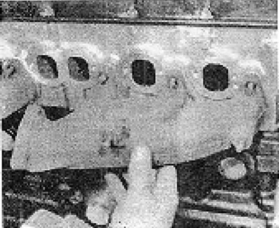
Photo 68.82. Installing the front sections of the exhaust manifold.
The information is posted on this website [VWmanual]
83. The general procedure for removing and installing manifolds is given in chapter 3, Section 14.
84. Always install manifolds with new gaskets (see photos).
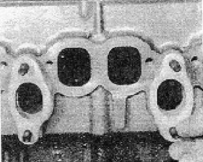
Photo 6B.84A. Installing new exhaust manifold gaskets...
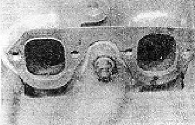
Photo of 6V.84V....and intake manifold.
85. Check the correct installation of heat shields and air ducts (see photos).
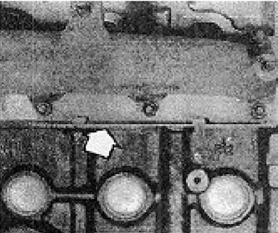
Photo 6B.85A. Lower front manifold shield (shown by the arrow)...
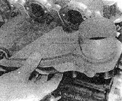
Photo 68.85V....upper collector shield...
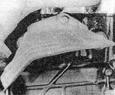
Photo 6B.85S....and rear heat shield.
Exhaust system
86. The exhaust system is very similar to that used on early models, but has different flange connections.
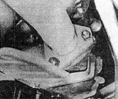
Photo 6B.86A. Front flange of the exhaust downpipe...
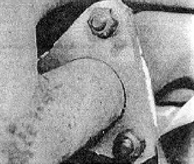
Photo of 6B.86B....and its rear flange.
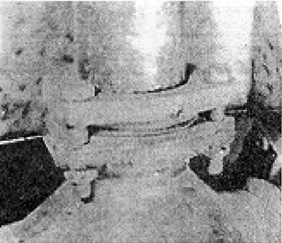
Photo 6B.86C. Typical flange connection of exhaust system pipes.
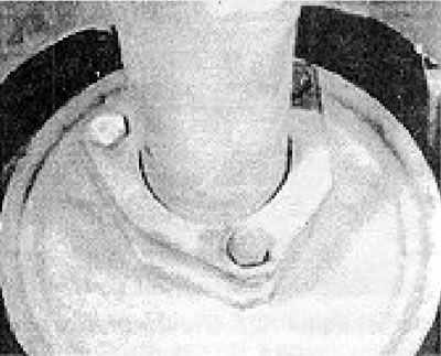
Photo 68.860. Muffler flange.
Visitor comments