



General description
58. The heater is installed on the lower surface of the intake manifold (see photo).
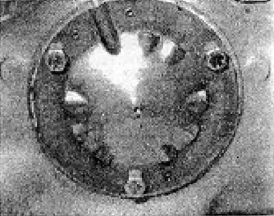
Photo 6B.58. Intake manifold heater.
59. The heater consists of an electric heating element controlled by a thermal switch, also located on the intake manifold (see photo), but in contact with the coolant of the water jacket of the manifold.
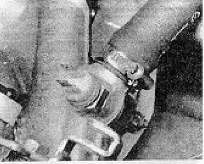
Photo 6B.59. Intake manifold heater thermal switch.
60. When the engine is cold, the thermal switch turns on the heating element.
61. As the engine warms up, the coolant temperature increases. Once it reaches a certain level, the thermal switch turns off the heating element.
62. When the engine is cold and the battery voltage is at least 11.5 V (the battery is well charged) measure the resistance between the connecting wire and a reliable ground, which should be 0.25-0.50 Ohm.
63 Similarly, you can check the thermal switch, which must be removed from the intake manifold and heated in hot water.
64. The resistance between the two terminals of the switch should be 0 at temperatures below approximately 55°C and infinity at temperatures above 65°C.
Visitor comments