



66. The system's control valve is located in the hot air duct that runs along the right side of the engine compartment. Hot air is collected from the exhaust manifold and directed into the main air intake system (See photo).
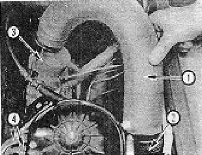
Photo 6B.66. Hot air supply system: 1 - Inlet channel; 2 - Control valve; 3 - Air intake shield; 4 - Vacuum hose connection points.
67. The control valve is actuated by a temperature-sensitive vacuum unit, which operates from the vacuum in the carburetor intake elbow.
68. To check the operation of the control valve, loosen its fastening clamps, disconnect the vacuum hoses from the valve and remove the valve from the air duct.
69. Check that the control valve is closed at temperatures above 17°C (see Fig. 13.41).
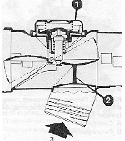
Figure 13.41. Sectional view of the hot air supply system control valve (section 6B): 1 - Control valve; 2 - Damper (in the closed position); 3 - Hot air.
70. Place the valve in the refrigerator and check that at temperatures below 17°C it is open at least 4/5 of its travel.
71. Apply vacuum to the vacuum hose and check that the valve opens and closes freely.
72. Before checking the temperature controller, make sure that the control valve is working properly.
73. The engine must be warm (but not hot).
74. Vacuum hoses must be connected.
75. Start the engine and let it idle.
76. Under these conditions the damper should be open (to check this, you need to disconnect the hot air hose).
77. Disconnect the temperature regulator vacuum hoses from the carburetor (see photo).
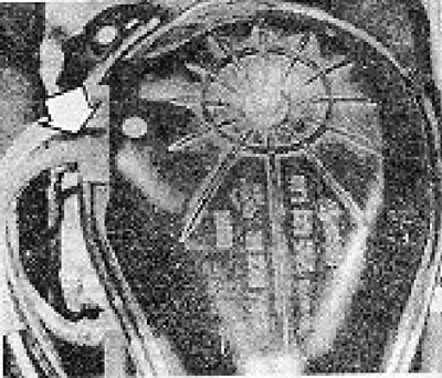
Photo 68.77. Air intake elbow and vacuum hoses connected to the hot air injection system control valve (arrow showings).
78. After 20 seconds the damper should close.
[The original information is posted on the resource: www.VWmanual.ru]
Visitor comments