



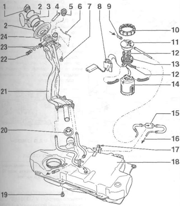
Fig. 3.23 a. Elements of the Polo Classic, Polo Estate power supply system:
1 - Lid; 2 - Fastening ring; 3 - Fuel tank flap; 4 - Ventilation tube; 5 - Gravity/Bypass Valve; 6-Connection to the "ground"; 7, 17, 19 - Bolts; 8 - Fuel level sensor; 9 - Fuel drain line; 10 - Nut; 11 - Flange; 12 - Corrugated tube; 13, 23 - Sealing rings; 14 - Fuel pump; 15 - Fuel intake line; 16 - Fuel filter; 18 - Fuel tank; 20 - Protective cover; 21 - Filler tube; 22 - Ventilation valve; 24 - Cup.
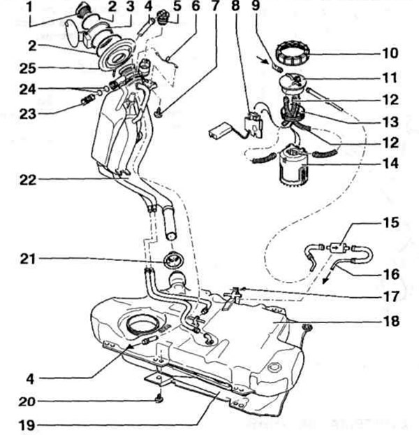
Fig. 3.23 b. Elements of the Caddy fuel system:
1 - Lid; 2 - Fastening ring; 3 - Fuel tank flap; 4 - Ventilation tube; 5 - Gravity/Bypass Valve; 6-Connection to the "ground"; 7, 17, 20 - Bolts; 8 - Fuel sensor; 9 - Fuel drain line; 10 - Nut; 11 - Flange; 12 - Corrugated tube; 13, 24 - Sealing rings;, 14 - Fuel pump; 15 - Fuel filter; 16 - Fuel intake line 18 - Fuel tank; 19 - Heat-protective casing; 21 - Protective cover; 22 - Filler tube; 23 - Ventilation valve; 25 - Cup.
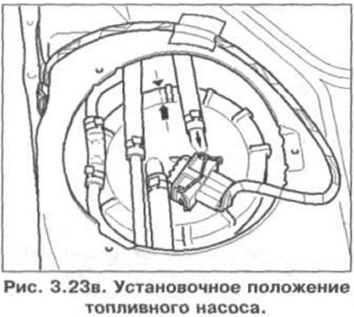
The installation position of the fuel pump is shown in Fig. 3.23 c. The marks on the flange must match the marks on the fuel tank.
(The original can be viewed on the portal: «vwmanual»)
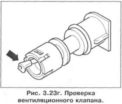
Checking the ventilation valve is shown in Fig. 3.23. The lever is in the free position - the valve is closed, the lever is pressed in the direction of the arrow - the valve is open.
Visitor comments