
Instructions: The hose connections are secured with spring and clamp clamps. Clamp clamps should always be replaced with spring clamps. The fuel supply hoses may only be secured to the engine with spring clips. The use of clamping collars and clamps with threaded fastening is not allowed.
Collision fuel cut-off system
Collision Fuel Shutoff should reduce the risk of vehicle fire after a collision by disabling the fuel pump. At the same time, thanks to this device, an improvement in comfort when starting the engine is achieved. When the door is opened, the fuel pump turns on for 2 seconds to pressurize the fuel system.
Removing and installing fuel gauge sender 2 -G169-
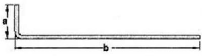
Bend the 80mm welding wire as shown. Dimension -a- = 10 mm, Dimension -b-: 70 mm. Unlock and disconnect wiring for fuel gauge sender 2 -G169-2-.
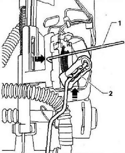
Push welding wire -1- -in direction of arrow- into recess under sensor. At the same time, push the fuel level sender 2 -G169- -2- out of the -direction of the arrow-.
Installation
Insert fuel level sender 2 -G169- into guides and push down until it clicks into place. Connect the connectors and check that they are securely fixed. Install the fuel delivery module.
Removing and installing fuel pump control unit -J539-
Note: Fitting location for fuel pump control unit -J533- is on fuel tank.
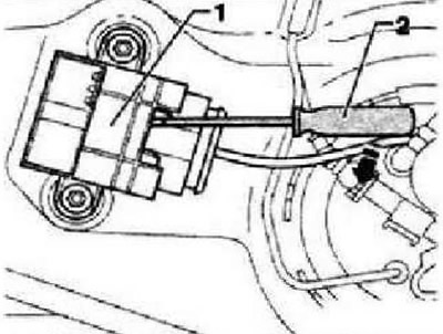
Fitting location for fuel pump control unit -J538-
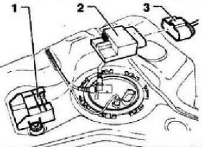
- 1 - Bracket for fuel pump control unit -J538-
- 2 - Fuel pump control unit -J538-
- 3 - connector
Remove the right, looking in the direction of travel, cover from the fuel supply module. Disconnect connector -1-.
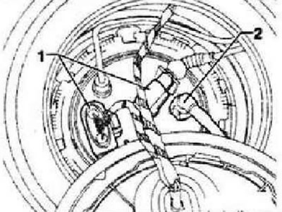
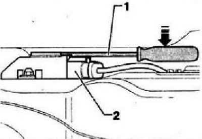
Insert a screwdriver -2- directly above the connector into the recess in the bracket. Move the screwdriver in the -direction of the arrow-.
Press the screwdriver downwards in -direction of the arrow- and at the same time remove the control unit at the connector from the bracket. Disconnect the control unit connector.
Installation
Plug connector -3- into control unit -2-. Push control unit -2- into bracket -1- until it clicks into place. Further installation is carried out in reverse order.
Repair of electronic engine power control (electronic accelerator drive)
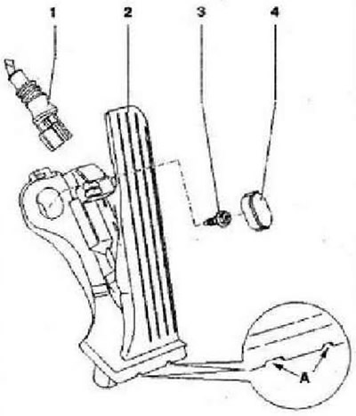
- 1 - Connector, black, 6-pin
- 2 - Accelerator position sender -G79- and accelerator position sender 2 -G185-. Holes -A- for puller. Remove to remove front panel trim and pedal cover
- 3 - 10 Nm
- 4 - Protective cap
Removing and installing the accelerator pedal module
Remove the pedal cover. Disconnect the connector from the gas pedal assembly. Remove the plug from the top of the gas pedal assembly. Unscrew the fixing bolt. To remove the accelerator pedal assembly, insert the release tool -T10238- as shown in the illustration as far as it will go into the holes.
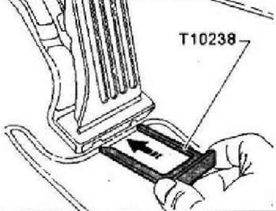
Carefully remove the accelerator pedal assembly vertically. Install in reverse order.
Activated carbon absorber system
Instructions: The hose connections are secured with spring and clamp clamps. Clamp clamps should always be replaced with spring clamps. We recommend using spring clip pliers -VAS 5024A- for mounting spring clips.
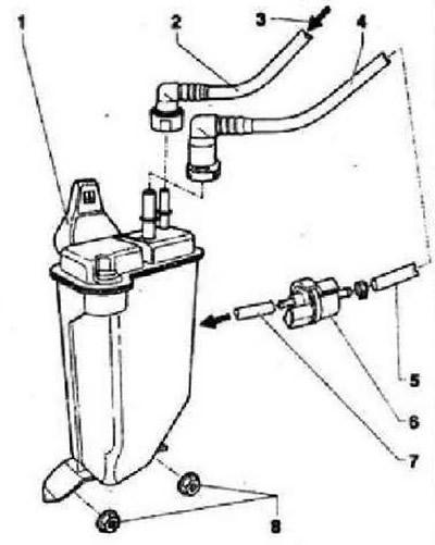
- 1 - Absorber with activated carbon. Fitting location: rear right wheel arch
- 2 - Connecting hose, remove the lock ring to remove
- 3 - From the fuel tank
- 4 - Vent line to canister solenoid valve 1 -N80-, clipped to fuel tank
- 5 - Ventilation line from activated carbon absorber
- 6 - Activated charcoal filter solenoid valve 1 -N80-, when the ignition is switched off, the valve is closed, when the engine is warm, it is controlled by a simulated signal from the engine control unit
- 7 - Connecting hose to the intake manifold, check the fastening
- 8 - 10 Nm
Visitor comments