



Contents: Removal ↓ Removal the power unit with a crane ↓ Removal the engine with a special…↓ Installation ↓ Tightening torques ↓
Fuel filter for diesel engines
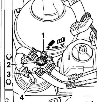
- 1 - spring clip;
- 2 - valve;
- 3 - fuel pipe;
- 4 - fuel pipe
The engine together with the gearbox is removed from the car downwards from the engine compartment. When removing the power unit, it is necessary to use a crane. The power unit can also be lowered using a special lift with engine holders.
To ensure sufficient working space under the vehicle, it is necessary to use four trestles or a vehicle lift with a platform or an inspection pit.
Depending on the manufacturing process and vehicle configuration, electrical wires, pipes and hoses may be arranged differently in the engine compartment. Therefore, before disconnecting electrical connectors and disconnecting pipes or hoses, it is recommended to mark them with adhesive tape.
Necessary special tools and auxiliary means:
- engine lifting crane;
- collet for band clamps;
- lifting grip;
- molybdenum disulfide based grease;
- torque wrench providing tightening torques of 5–50 Nm;
- torque wrench providing tightening torques of 40–200 Nm;
- clamp.
Removal
Warning: All clamps and straps that are unscrewed or cut when removing the engine must be installed in the same places when assembling the engine, so their installation position can be marked with adhesive tape. When disconnecting electrical connectors, release the retaining wire and then disconnect the electrical connector.
1. Remove the ground cable from the battery.
Warning: When the battery is disconnected, the contents of the memory cells, such as the radio code, are erased. Without the code, the radio can only be reconnected by the manufacturer.
2. Remove the battery.
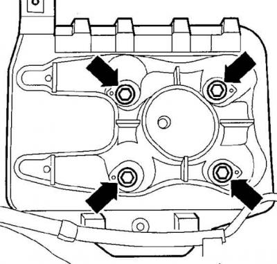
3. Unscrew the battery holders and remove them (the arrows indicate the nuts that secure the battery holder).
4. Remove the starter.
5. Remove the lower engine compartment splash shield.
6. Unscrew the left and right drive shafts from the transmission flange. Using soft wire, tie the ends of the drive shafts to the anti-roll bar or body.
7. Drain the coolant from the cooling system.
TDI engine
8. Remove the pipe connecting the charge air radiator and the intake manifold.
SDI Engine
9. Remove the pipe connecting the charge air radiator and the air filter.
10. Loosen the tension and remove the poly V-belt.
Remove the starter.
11. Unscrew the power steering pump from the bracket and use a soft wire to hang it from the body. Do not disconnect the hoses from the pump or kink the hoses.
Cars with air conditioning
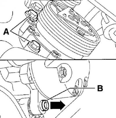
12. Unscrew the air conditioner compressor mounting screws and, without disconnecting the hoses from it, move the compressor to the side and secure it with soft wire (A - upper bolt, B - lower bolt).
Warning: Do not disconnect the air conditioning system pipes.
13. Remove the exhaust pipe and catalytic converter.
14. Loosen the clamps, mark and disconnect the vacuum hose and air intake pipe from the turbocharger.
15. Disconnect all electrical connectors from the engine and transmission.
16. Release the spring clip (1) (see picture Fuel filter for diesel engines) and remove the hose assembly from the valve (2). Loosen the clamps and remove the fuel hoses from the fittings (3 and 4). Cover the ends of the fuel hoses with foil or suitable plugs to prevent dirt from getting into them.
17. Disconnect the coolant supply hoses to the heater radiator from the engine compartment bulkhead.
18. Disconnect the hoses leading to the expansion tank from the engine and body and move them to the side.
19. Disconnect the cooling system hoses from the radiator.
20. Lift and secure the expansion tank together with the bracket.
Cars with manual transmission
21. Disconnect the shift mechanism and clutch slave cylinder from the transmission.
Warning: After removing the clutch slave cylinder, do not press the clutch pedal.
Cars with automatic transmission
22. Unscrew the brackets securing the power steering pressure line to the gearbox. Disconnect the automatic transmission control cable from the gearshift lever.
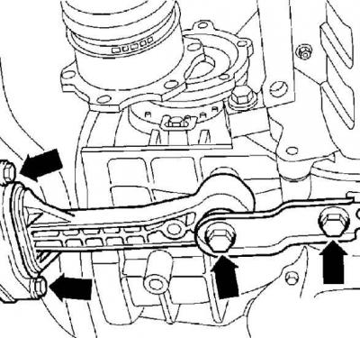
23. At the bottom of the engine compartment, unscrew the bolts (indicated by arrows) and remove the pendulum support that supports the engine and gearbox.
24. Raise the vehicle so that the distance between the vehicle and the ground is at least 60 cm.
Removal the power unit with a crane
1. Place a 30 x 40 cm wooden deck approximately 15 cm thick under the engine oil pan.
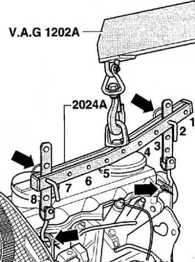
2. Using the special device, hook the power unit onto the lifting eyes of the power unit.
3. If there is no special device to support the engine, use a chain.
4. Raise the lifting mechanism so that the weight of the power unit is supported by the lifting mechanism.
Removal the engine with a special holder
The special holder is a VAG 1383A hydraulic lift with a T10012 engine holder.
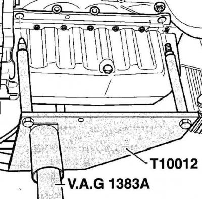
1. Install a special engine holder from below into the hole near the oil pan and secure the engine with nuts, tightening them to a torque of 25 Nm. Raise the engine holder so that the weight of the power unit is supported by the holder.
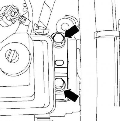
2. Remove the bolts securing the right upper powertrain support (indicated by arrows).
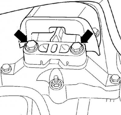
3. Unscrew the bolts (indicated by arrows) and remove the left support of the power unit.
4. Check that all electrical connectors and hoses connecting the engine and gearbox to the body are disconnected.
5. When removing the engine using a crane, move the power unit forward and carefully lower it onto a wooden stand. Secure the power unit so that it cannot tip over.
6. If necessary, disconnect the gearbox from the engine.
Installation
1. Check the condition of the powertrain mounts and hoses for cracks or wear and replace them if necessary.
2. If the transmission has been disconnected from the engine, check the condition of the clutch.
3. Install the power unit into the engine compartment and align it as follows.
4. Secure the right powertrain mount with new bolts, hand tightening them at this stage.
5. Secure the powertrain pendulum support with new bolts, tightening them by hand at this stage.
6. Tighten the power unit mounts to the required torque (see table Tightening torques).
Warning: Unless specified, standard bolt tightening torques are as follows: M8 – 20 Nm, M10 – 45 Nm and M12 – 60 Nm.
7. If the compressor was removed, secure it with bolts, tightening them to a torque of 45 Nm.
8. Install the servo pump.
9. Install the starter.
10. Install the poly V-belt and adjust its tension.
TDI diesel engine
11. Install the pipe connecting the charge air radiator and the intake manifold and secure it with clamps.
SDI diesel engine
12. Install the pipe connecting the intake manifold and air filter.
13. Install the exhaust pipe and catalytic converter with new gaskets.
14. Install the right and left drive shafts.
15. Connect the coolant supply hoses to the heater radiator on the engine compartment bulkhead and secure them with clamps.
16. Install the radiator fan.
Cars with manual transmission
17. Connect the shift rods to the gearbox. Install the clutch slave cylinder.
Cars with automatic transmission
18. Install and secure the power steering pressure pipe bracket to the gearbox. Connect the control cable to the gearbox and adjust it.
19. Connect the disconnected electrical connectors and pipes to the power unit, securing them with clamps.
20. Connect the fuel hoses to the fittings (3 and 4, see figure Fuel filter for diesel engines) fuel filter. The arrow on the fuel filter indicates the direction of fuel flow.
21. Replace and secure the battery holder.
22. Reinstall the battery, but do not connect the ground cable to it at this stage.
23. Install the valve (2) in place and secure it with the spring clip (1, see figure Fuel filter for diesel engines).
24. Check that electrical connectors and lines are connected correctly to the power unit.
25. Check the oil level in the engine and gearbox and top it up if necessary.
26. Fill the cooling system with coolant.
27. Install the upper engine cover.
28. Install the lower engine compartment splash shield.
29. Connect the ground wire to the battery.
Warning: Activate the electric windows, set the clock and enter the code into the radio.
30. Start and warm up the engine to normal operating temperature.
31. Check the oil and coolant levels and the tightness of all connections.
32. Visually check that the adjustments are correct.
Tightening torques
| Connection points | Tightening torques |
| Engine to bracket | 60 Nm + turn by 90° |
| Gearbox to bracket | 60 Nm + turn by 90° |
| Pendulum support to the gearbox | 40 Nm + turn by 90° |
| Pendulum support to the body | 20 Nm + turn by 90° |
Visitor comments