
Caution: For any assembly work, in particular in the engine compartment due to the tight layout, the following must be observed. Lines of all kinds (e.g. fuel, hydraulic, activated charcoal absorber, cooling systems, refrigerant circuits, lines and hoses of the brake system, vacuum), as well as electrical wires must be laid so. how they were originally laid out. To avoid damage, ensure sufficient clearance to all moving and hot parts. When the engine is warm, the cooling system is under pressure. If necessary, the pressure must be relieved before repair work. The hose connections are secured with spring clamps. When repairing, use only spring clamps. When installing, route the coolant hoses without tightening them. Make sure they don't touch other components (observe the markings on the radiator pipe and hose).
Elements of the cooling system installed on the body
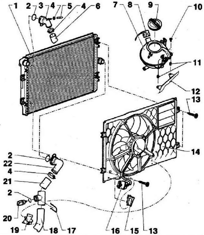
- 1 - Cooler, after replacement, change the coolant
- 2 - O-ring, replace if damaged
- 3 - Fitting, to remove, disconnect the clamp
- 4 - Spring clamp
- 5 - Coolant hose
- 6 - Radiator hose, upper, to the fitting on the MCC
- 7 - Expansion tank. Check cooling system for leaks
- 8 - connector
- 9 - Lid. Check for tightness. At a pressure of 1.4-1.6 bar, the safety valve in the lid should open
- 10 - 5 Nm
- 11 - Plastic inserts, for fastening screws
- 12 - Bracket
- 13 - 5 Nm
- 14 - Air intake for radiator fan -V7- with cooling fan control unit -J293-. Radiator fan -V7- and air intake must only be replaced as a set when replacing. Heat shields must be fitted to prevent damage to the radiator grille from the thermal energy of the exhaust system. Tightening torque for heat shields: 3 Nm
- 15 - Connector bracket
- 16 - Connector
- 17 - Latches
- 18 - Coolant hose, lower, to thermostat fitting
- 19 - Hose routing
- 20 - Radiator outlet coolant temperature sender -G83-
- 21 - Coolant hose, lower, to thermostat fitting
- 22 - Connecting pipe, to remove, disconnect the clip
Elements of the cooling system installed on the engine (thermostat related)
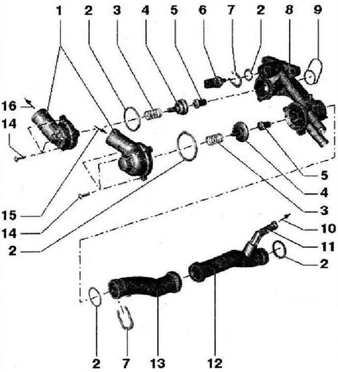
- 1 - Connecting pipe
- 2 - O-ring, replace
- 3 - Spring
- 4 - Pusher, do not warp during installation
- 5 - Thermostat. Do not mix up thermocouples! Opening start: thermocouple (on the bottom picture): 80°С, thermocouple (in the top picture): 96°C
- 6 - Coolant temperature sender -G62-, relieve pressure in cooling system before removing if necessary
- 7 - Mounting bracket, check the security of fastening
- 8 - Thermostat housing, 10 Nm
- 9 - Shaft seal, replace
- 10 - To expansion tank
- 11 - Connecting fitting
- 12 - Coolant pipe, to remove, dismantle the thermostat housing, to remove, dismantle the compressor
- 13 - Coolant pipe, to remove, dismantle the thermostat housing, to remove, dismantle the compressor
- 14 - 5 Nm
- 15 - From the bottom of the radiator
- 16 - To the radiator from above
Cooling system hose connection diagram
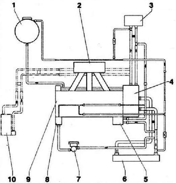
- 1 - Expansion tank
- 2 - Intake manifold
- 3 - heater heat exchanger
- 4 - Thermostat housing
- 5 - Engine oil cooler
- 6 - Cooler
- 7 - Coolant circulation pump -V50-
- 8 - Turbocharger
- 9 - Cylinder head / cylinder block, after replacement, drain the old and fill in new coolant
- 10 - Auxiliary heater, additional equipment
Visitor comments