
Poly V-belt storage
Caution: Before installing the V-ribbed belt, check that all the components driven by it are securely fastened (generator, air conditioner compressor). When installing the V-ribbed belt, pay attention to the direction of travel and the correct fit on the pulleys and tensioning elements. First put the V-ribbed belt on the crankshaft pulley. Lastly, pull the belt over the tension roller. Further installation and assembly is carried out in the reverse order of removal. Fill with coolant. Upon completion of work required. Start the engine and check the movement of the drive belt.
Belt drive with air conditioner compressor
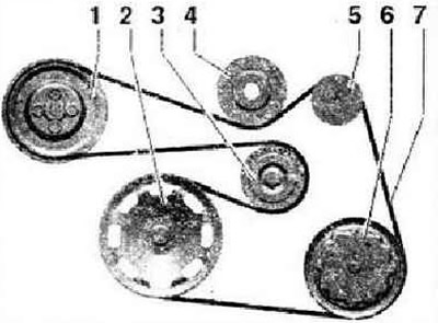
- 1 - Belt pulley - coolant pump
- 2 - Belt pulley - crankshaft
- 3 - Tension roller
- 4 - Tension roller
- 5 - Belt pulley - generator
- 6 - Belt pulley - air conditioner compressor
- 7 - V-ribbed belt
Belt drive compressor
Note: The belt pulley for the magnetic clutch of the compressor -N421- is located behind the belt pulley - coolant pump. The V-ribbed belt -4- passes through the belt pulley of the electromagnetic compressor clutch -N421-.
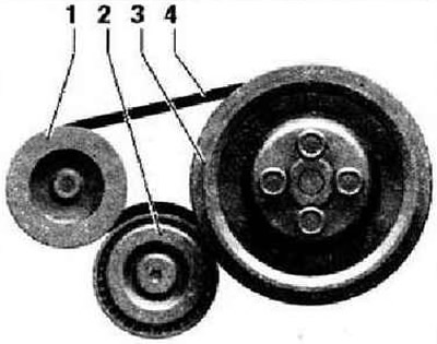
- 1 - Belt pulley - compressor
- 2 - Tension roller
- 3 - Belt pulley for coolant pump with belt pulley for electromagnetic compressor clutch -N421-
- 4 - V-ribbed belt
Removal and installation of a sealing flange and a flywheel/driven disk
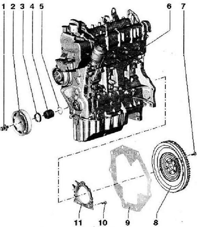
- 1 - Mounting screw, replace. The contact surface of the bolt head must be free of oil and grease, insert after lubricating with oil (carving). Secure the belt pulley against twisting with counterhold 3415, the tightening angle can be measured with a standard measuring disc, e.g. Hazet 6690
- 2 - Belt pulley. The mating surfaces must be free of oil and grease; when removing or installing, fix with a key 3415 against twisting
- 3 - Shaft seal, replace
- 4 - Bearing sleeve. Mating surfaces must be free of oil and grease
- 5 - O-ring, replace
- 6 - Cylinder block
- 7 - 60 Nm and tighten by 90°
- 8 - Flywheel / driven disk. To remove or install, secure flywheel with locking key -T10044-
- 9 - Intermediate plate, must sit on the mounting sleeves, not be damaged / bent during installation work
- 10 - 12 Nm, replace
- 11 - Sealing flange with sensor wheel and lip seal. Tightening torque for engine speed sender -G28-: 5 Nm. The sealing flange must only be replaced complete with lip seal and wheel
Cylinder head
Instruction: When installing a new cylinder head, before installing the camshaft housing, it is necessary to lubricate with engine oil all contact surfaces between the bearing elements, roller levers and the camshaft bed. The plastic pads included in the repair kit to protect open valves may only be removed immediately before installing the block head. When replacing the cylinder head, you should also drain the old and fill in new coolant. All seating and working surfaces must be lubricated before installation.
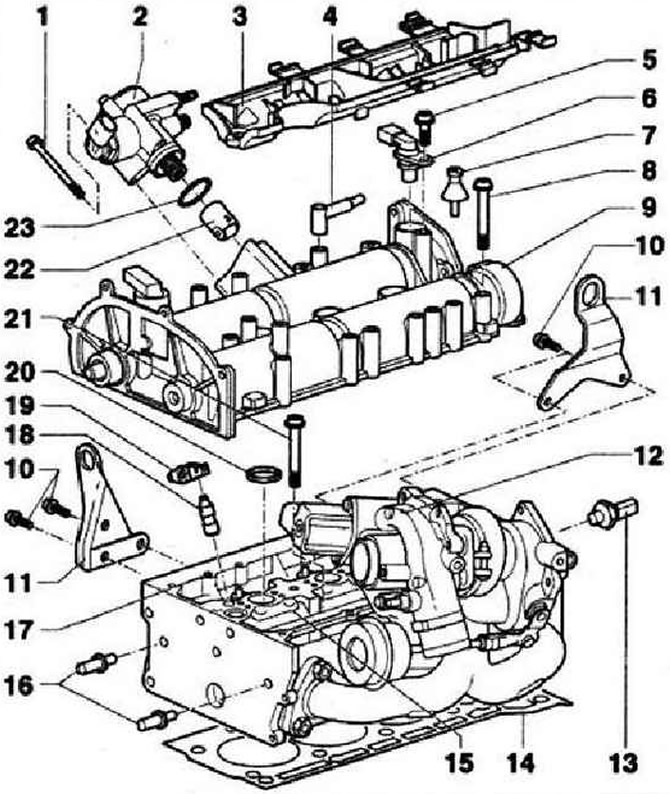
- 1 - 8 Nm
- 2 - High pressure pump for fuel system, with fuel pressure control valve -N276-
- 3 - Wiring box, screw to the camshaft housing with a torque of 8 Nm
- 4 - To the air filter
- 5 - 10 Nm
- 6 - Hall sender -G40-, with lip seal. If the sealing ring is damaged, replace it
- 7 - Spacer bolt, 6 Nm
- 8 - 10 Nm and tighten by 90°, replace, tighten from center to edges
- 9 - Camshaft housing, remove the remnants of the old sealant, carefully clean the seating surfaces; they must be free of oil and grease, lubricate D 188 003 A1 before installation. When installing, slide vertically from above onto the spacer bolt and dowel pins
- 10 - 20 Nm
- 11 - Hanging eye
- 12 - Turbocharger
- 13 - Oil pressure switch -F1-, 25 Nm. If there is leakage, bite off and replace the lip seal
- 14 - Cylinder head gasket, replace, metal gasket. After replacement, change the coolant
- 15 - Cylinder head, the seating surface must be free of oil and grease, after replacement, change the coolant
- 16 - Guide bolt, 20 Nm
- 17 - Locating pin
- 18 - Support element, do not change places, with hydraulic compensator, lubricate the working surface with oil
- 19 - Roller lever, check the roller bearings for ease of rotation, lubricate the working surface with oil. For installation, clip onto the support element with a fixing clip
- 20 - Sealing ring. When removing and installing the camshaft bearing housing, it is necessary to take into account the different seals, replace the 4 pcs used in the MCC
- 21 - Main screw, replace. Observe the assembly instructions and sequence when loosening and tightening
- 22 - Roller pusher. Lightly coat work surfaces with engine oil
- 23 - O-ring, replace, moisten with engine oil before replacing
Checking the cylinder head for distortion
The maximum allowable curvature of the contact plane: 0.05 mm.
Valve timing adjustment
Remove the distributor cover. To rotate the crankshaft, insert the support sleeve, the crankshaft pulley -2- and the crankshaft bolt -3-, then screw in the bolt (use counterholder 3415).
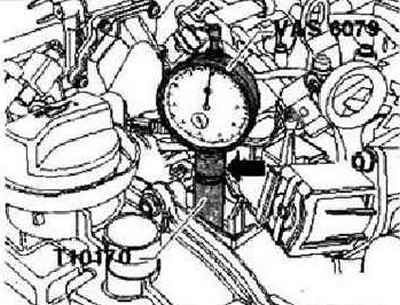
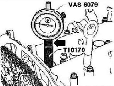
Remove the spark plug of the first cylinder. To do this, use puller -T10094 A- and spark plug wrench 3122 B. Screw dial gauge adapter -T10170- into spark plug socket as far as it will go. Insert dial gauge -VAS 6079- with extension -T10170/1- as far as it will go and press in with nut -arrow-.
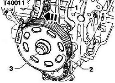
Rotate the crankshaft in the direction of engine rotation to the TDC of cylinder 1. Note the position of the small hand on the dial gauge. Then turn the crankshaft against the direction of engine rotation by 45°. Press tensioner bar -1- in direction of arrow and secure piston with locking pin -T40011-. Mark the running direction of the timing chain -3- with a felt-tip pen.
Instruction: The central bolt of the phase shifter -2- has a left-hand thread.
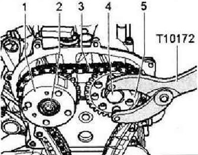
Remove bolts -2- and -4- and remove phase shifter -1- from timing chain -3-. Use counterholder -T10172- to hold. Reattach phase shifter -1-. Replace bolts -2- and -4- and tighten bolt -2- to 40 Nm and bolt -4- to 50 Nm (use counterhold -T10172-).
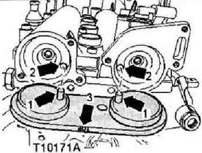
Rotate intake and exhaust camshafts until camshaft clamp -T10171 A- is fully seated in bores in camshafts. Locking pins -arrows 1- must engage in holes -arrows 2-. mark "TOR"-arrow 3- must be visible from above.
Instruction: When scrolling, the camshafts must not be displaced along the axis.
To secure the camshaft clamp -T10171 A-, screw the M6 bolt into the appropriate hole -arrows- by hand; do not tighten.
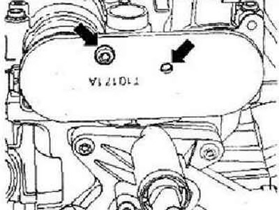
Instruction: Note that the camshaft clamp -TYu171A- has different attachment points.
Loosen the camshaft sprocket bolts. To do this, it is essential to use the counterholder -T10172-.
Note: The camshaft lock -T10171 A- must not be used as a counter key.
Remove one camshaft sprocket. Place the timing chain, observing the direction of travel, on the camshaft sprockets and fit the removed sprocket again. Screw in the camshaft bolts until the sprockets still turn on the camshafts. Tension timing chain by pulling out locking pin -T40011-. Rotate the crankshaft in the direction of engine rotation to TDC 1 cylinder. Permissible deviation from TDC 1 cylinder:±0.01 mm.
Instruction: If the crankshaft was rotated beyond TDC by more than 0.01 mm, it should be turned again against the direction of engine rotation by about 45°. Finally, bring the crankshaft in the direction of engine rotation to the TDC of cylinder 1.
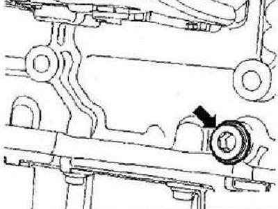
Unscrew the plug -arrow- in the crankcase.
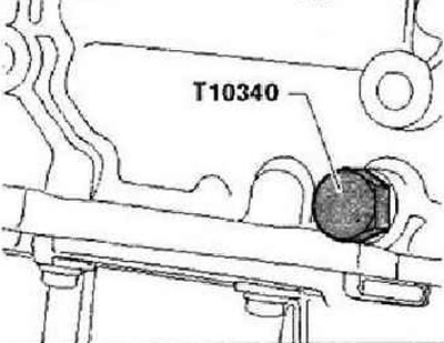
Screw fixing bolt -T10340- into engine crankcase as far as it will go. Tighten locking bolt -T10340- to 30 Nm. Locking bolt -T10340- locks crankshaft in direction of engine rotation.
Hold camshaft sprockets -1- and -5- in position with counterhold -T10172- and tighten bolts -2- (left hand thread) with a tightening torque of 40 Nm and -4- by 50 Nm.
Note: When tightening the camshaft bolts, the crankshaft must not turn and the timing chain -3- must remain tensioned on both sides.
Remove camshaft clamp -T10171 A-. Unscrew fixing bolt -T10340- from crankcase. Rotate the crankshaft in the direction of engine rotation two revolutions at TDC 1 cylinder. Permissible deviation from TDC 1 cylinder:±0.01 mm. Insert the camshaft clamp -T10171 A- into the holes in the camshafts as far as it will go. If camshaft clamp -T10171 A- cannot be inserted. Repeat adjustment. If the camshaft clamp -T10171 A- is inserted. Screw fixing bolt -T10340- into engine crankcase as far as it will go. Tighten locking bolt -T10340- to 30 Nm. Remove camshaft clamp -T10171 A-, hold camshaft sprockets firmly with counterhold -T10172- and tighten bolts -2- (left hand thread) and -4- with a 1/4 turn hard key.
Instructions: The central bolt of the phase shifter -2 has a left-hand thread. When tightening the bolts, the sprockets must not rotate on the camshafts.
Further installation and assembly is carried out in the reverse order of removal. In doing so, the following must be taken into account.
Note: The fixing bolt -T10340- remains in the crankcase until the crankshaft pulley is installed.
Installing the regulator housing. Install the crankshaft pulley. Install poly V-belt. Replace the lip seals on the camshaft plugs and lubricate them with oil before installation.
Visitor comments