



- parts must be clean;
- always lubricate any rotating or sliding parts. This should be done before assembly (and not after the parts have already been installed), then the oil will get to all the necessary places. It is especially important to generously lubricate the pistons, piston rings and cylinder walls with engine oil before assembly;
- clean all parts of the cylinder block thoroughly if the engine has been completely disassembled. When partially disassembling, make sure that no foreign bodies get inside the disassembled engine or into its cavities. Plug all openings with clean rags to avoid this;
- blow out the oil passages with compressed air. If you do not have this opportunity, then clean the oil passages and holes with a wooden stick, but under no circumstances do this with metal objects.
The adjustment and control data table shows the wear limits of most moving parts. If you have any doubts about a part or the wear limit is about to be reached, it is better to replace such a part to avoid repeated disassembly of the engine.
The following describes the assembly of the engine after its complete disassembly. In this case, we assume that all engine parts have been repaired or replaced in accordance with the instructions given in the following sections. In addition, we assume that individual structural groups, such as the cylinder head, are already assembled.
Install the oil injectors into the cylinder block. Tighten the injector mounting bolts to 10 Nm.
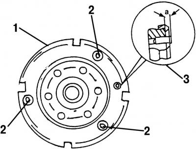
Fig. 383. Flywheel: 1 - toothed rim; 2 - toothed rim mounting bolts; 3 - Set screw (must protrude a distance a)
Screw on the toothed rim of the crankshaft speed sensor. The bolts should always be replaced with new ones. A dowel pin is inserted into the crankshaft (Fig. 383), this pin should protrude from the surface of the crankshaft by a certain amount (2.5-3.0 mm). Therefore, before tightening the toothed rim (torque 10 Nm), measure the distance the mounting pin protrudes.
Lubricate all crankshaft bearing surfaces with engine oil and place the shaft on the inserted bearing shells. Carefully place the crankshaft inside the bearings and install adjusting washers to the left and right of the middle bearing. The oil grooves of the adjusting washers should be located against the bearing surface of the crankshaft.
Install into the cylinder block in accordance with the marks on the main bearing caps (the bearing shells must be inserted and well lubricated) and beat them with a plastic or rubber hammer.
Screw in the main bearing cap bolts and tighten them evenly from the center outward to a torque of 65 N·m. From the final position, turn each bolt, again from the center outward, another 90° (quarter turn).
Caution: Use only new bolts.
Check the crankshaft end play as described in p. 17.9.1.
Install the pistons and connecting rods (see paragraph 17.5.5).
Press the new seal from the outside into the intermediate shaft flange.
Lubricate the intermediate shaft journals and insert the intermediate shaft into the crankcase. Install a new sealing ring into the shaft flange and install the flange. Tighten both bolts to 25 N·m.
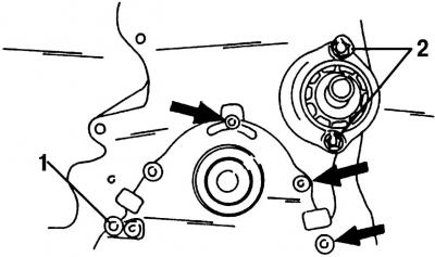
Fig. 384. The bolts of the crankshaft oil seal 1 and the intermediate shaft flange 2 must be tightened to a torque of 25 Nm
Knock out the seal from the front seal housing. Insert the housing without the seal into the cylinder block. Tighten the 4 bolts to 25 N·m. Fig. 384 shows how to attach it.
Install a new front oil seal as described in section 17.9.3.
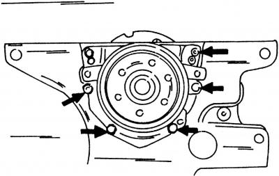
Fig. 385. The seal flange shown on the rear of the engine must be replaced together with the seal. Tighten the bolts (shown by arrows) torque of 10 Nm
After this, screw on the rear oil seal housing with a new gasket. Tighten the bolts shown in Figure 385 to 10 Nm.
Caution! The sealing ring cannot be replaced separately - the entire gland flange must be installed.
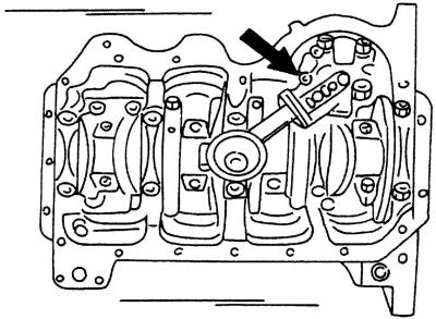
Fig. 386. Installed oil pump. Tighten the bolts to 25 N·m
Attach the oil pump to the lower part of the crankcase (2 bolts, 25 Nm). Fig. 386 shows their mounting locations.
Install the oil pan with a new gasket. Tighten the bolts in a circle to 20 N·m.
Install the engine intermediate plate (3 bolts, 10 Nm).
Install the flywheel. The bolts should be tightened evenly in a crisscross pattern to a torque of 60 Nm. From the final position, turn all bolts a further 90° (quarter turn) (without using a torque wrench).
Caution: Use only new bolts.
Install the clutch as described in the relevant section. The flywheel must be fixed in a stationary position.
Install the crankshaft gear. Lubricate the bolt. Fix the crankshaft in a stationary position, preventing the flywheel from turning, and tighten the bolt to a torque of 90 N·m. From the final position, turn the bolt another 90° (without using a torque wrench).
Caution: Use a new bolt.
Place the intermediate shaft gear wheel on the shaft. The shaft should already have a woodruff key. Lock the gear wheel in a stationary position and tighten the bolt to 45 Nm.
Install the components removed from the left side of the engine. Tighten the crankshaft position sensor to 10 N·m and the crankcase ventilation connection to 25 N·m.
Install the vacuum pump with a new sealing ring (20 Nm).
Install the oil filter base with a new gasket (3 bolts, 25 Nm).
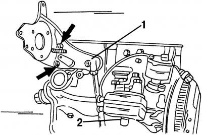
Fig. 387. Installing bracket 1 of the high-pressure fuel pump and oil cooler 2
Screw on bracket 1 for fastening the high-pressure fuel pump (Fig. 387) with three bolts. Tighten the bolts to a torque of 20 N·m, then tighten by another 90°. Install the oil radiator with a new gasket. Tighten the nut at the bottom of the oil radiator to a torque of 25 N·m.
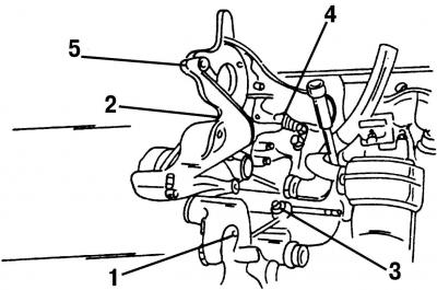
Fig. 388. The bolts of the supporting bracket for fastening the units are located in the places shown, the numbers indicate the order of tightening the fastening bolts
Install the component support bracket. Replace the cylinder block sealing ring. Install the bracket on the guide holes and screw in the five bolts. Attach the coolant hose to the oil cooler. At the same time, also screw in the oil filter (subsection 18.3). Tighten the unit support bracket bolts in the sequence shown in Fig. 388 to 25 Nm.
Measure how far the pistons protrude (see paragraph 17.5.3) and select the cylinder head gasket according to the obtained measurement value.
Install the cylinder head (see p. 17.3.6).
Install the intake manifold with a new gasket and tighten it with six bolts (25 Nm).
Install new exhaust pipe gaskets with their curves facing upwards, install the pipe together with the turbocharger and screw them on (25 Nm). Install the oil recirculation hose, tighten the hollow ring joint bolt (30 Nm) and screw on the heat shield (two nuts).
Connect the turbocharger oil line (union nut). Tighten it to a torque of 25 N·m. Tighten the hollow bolt in the cylinder head to a torque of 25 N·m.
Tighten the EGR connecting pipe (25 Nm).
Connect the additional heating plug.
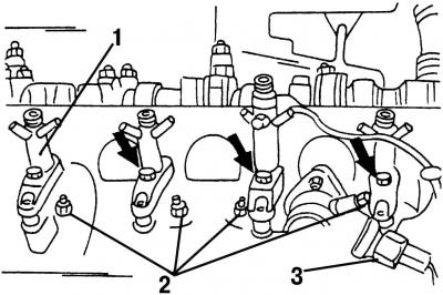
Fig. 389. Installing injectors and glow plugs: 1 - tension holder, 22 Nm; 2 - glow plugs, 15 Nm; 3 - wire tip
Install the injectors together with the solderings. Tighten the solderings to a torque of 22 N·m. Fig. 389 shows where the injectors are attached.
Screw in the glow plugs. Tighten them to a torque of 15 Nm (Fig. 389). Connect the coolant temperature sensor connector on the right side.
Bolt on the glow plug electrical bus and install the oil drain hoses.
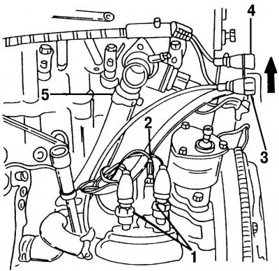
Fig. 381. Parts that need to be removed: 1 - oil pressure switch; 2 - oil temperature sensor; 3 - crankshaft position sensor; 4 - needle lift sensor; 5 - coolant hose
Connect all wires to the sensors (Fig. 381). The connector block with the blue/black wire is installed on the blue oil pressure switch, the connector block with the yellow/black wire is installed on the gray oil pressure switch.
Install the fuel injection pump (see the relevant section).
Install the inner toothed belt guard (2 bolts in the cylinder head, 1 bolt on the high pressure fuel pump).
Install the fuel injection pump toothed wheel. First, put on the woodruff key. Fix the toothed wheel in a stationary position and tighten the nut to a torque of 55 N·m. Also tighten the toothed drive belt tension roller without tightening it completely.
Install the poly V-belt as described in the relevant section. After securing the camshaft gear in a stationary position, tighten the mounting bolt to a torque of 45 N·m.
Connect the fuel supply lines to the injection system. Tighten the union nuts to 25 Nm. Connect the nearby plug connector.
Install the cylinder head cover. Use a new gasket. Tighten the nuts to 10 Nm and fit the protective caps. Connect the ventilation hose. After that, fit the toothed belt guard now.
Install the front engine mount clamp. Tighten the bolts to 60 Nm.
Install the generator (25 Nm).
Place the crankshaft pulley through the dowel pin onto the crankshaft timing gear and tighten the bolts. Tighten the bolts to 25 N·m. Tighten the water pump pulley (23 N·m).
Tighten the drive shaft thrust bearing (43 Nm) and the turbocharger support clamp (25 Nm).
Perform all work not specifically mentioned in the reverse order of the disassembly process.
Visitor comments