



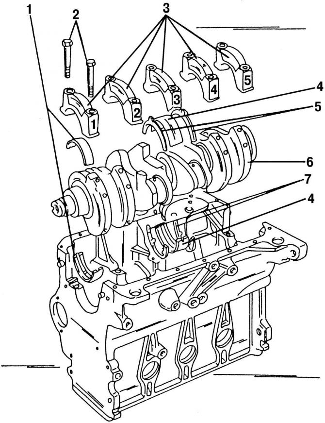
Fig. 440. Crankshaft bearings: 1 - bearing shells No.1, 2, 4 and 5. Shells with lubrication grooves are located in the cylinder block, shells without lubrication grooves are located in the bearing caps; 2 - cover bolts, 65 Nm + 90 Nm; 3 - main bearing caps, cap No.1 is located on the pulley side, cap No.3 has recesses for adjusting washers; 4 - bearing shells No.3. The shell with a lubrication groove is located in the cylinder block, the shell without lubrication grooves is located in the bearing cover; 5 - adjusting washers for bearing No.3; 6 - crankshaft; 7 - adjusting washers of bearing No.3, located in the cylinder block
Before removing the crankshaft, which can only be done with the engine removed, measure the axial clearance to know during assembly whether it is necessary to change the adjusting washers on the middle main bearing (Fig. 440).
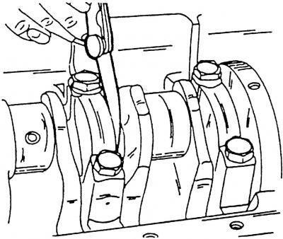
Fig. 441. Measuring the axial clearance of the crankshaft using a feeler gauge
The original article is available at (www.VWManual.ru)
Insert a feeler gauge on the middle bearing (number 3) between the crankshaft web and the inserted adjusting washer, as shown in Fig. 441, and check the axial clearance, which should be between 0.07 and 0.17 mm. The largest clearance should not exceed 0.37 mm.
Make sure that the axial clearance is completely selected, for which purpose rest the lever (it is best to use a wooden handle of any tool to avoid damage) into the cheek of the crankshaft and use it to push the shaft aside. By inserting feeler gauges of different thicknesses, set the exact gap size.
The axial clearance can be measured using an indicator, which should be attached to the end face of the cylinder block, and the measuring finger should be placed on the end face of the crankshaft. Then press the crankshaft in the direction of the indicator. Set the indicator to zero and press the shaft in the opposite direction. Look at the clearance value on the indicator.
Visitor comments