



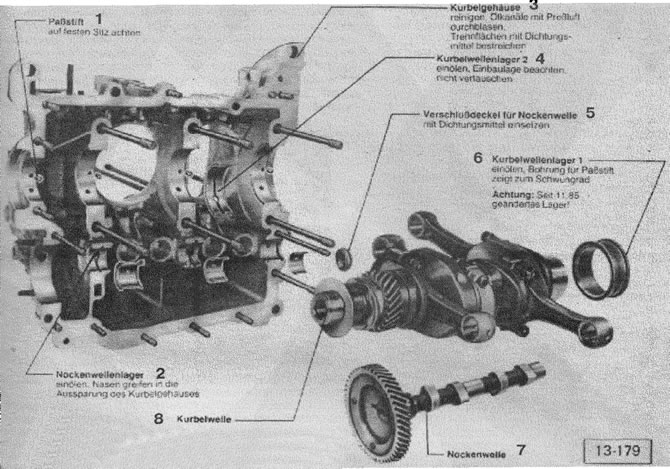
1. Pin to ensure a secure fit; 2. Lubricate the camshaft bearing with engine oil, the protrusions enter the crankcase recess; 3. Clean the engine crankcase, blow out the lubrication channels with compressed air, cover the contact surfaces with a sealing mass; 4. Lubricate the crankshaft bearing 2 with engine oil, keep the installation position, do not change; 5. Insert the camshaft plug with sealing compound; 6. Lubricate the crankshaft bearing 1 with engine oil, the pin hole faces the flywheel. Attention: changed bearing from 11.85! 7. Camshaft; 8. Crankshaft
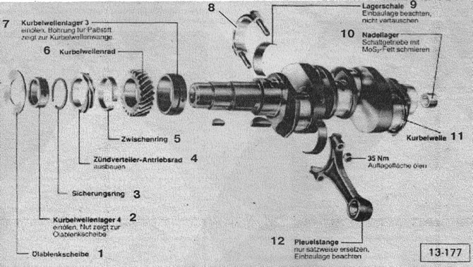
1. Oil deflector; 2. Main bearing No. 4; 3. Retaining ring; 4. The drive gear of the ignition distributor drive; 5. Distance ring; 6. Camshaft drive gear; 7. Main bearing No. 3; 8. Connecting rod bearing cap; 9. Insert connecting rod bearing; 10. Needle bearing (lubricate with molybdenum grease MOS2); 11. Crankshaft; 12. Connecting rod
Axial play during installation should be 0.07-0.13 mm. When the wear limit is reached (0.15 mm) play should be adjusted.
Examination
End play is checked with the engine installed without removing the flywheel.
Attach the corresponding dial indicator stand to one of the two engine mount studs and attach the indicator gauge to the flywheel.
Move the crankshaft in the axial direction in both directions and take readings from the dial indicator scale.
Attention: Since November 1985, modified crankshaft bearing shells have been installed. In connection with this, seals and spacers have also been changed.
Adjustment on engines manufactured before November 1985
Install flywheel with only 2 spacers. The crankshaft oil seal and flywheel O-ring remain removed.
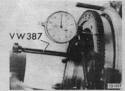
Fix the dial indicator with the stand on the engine crankcase.
Move the crankshaft in the axial direction in both directions and take readings from the dial indicator scale.
Calculate the thickness of the 3rd spacer. Axial play according to dial indicator minus (-) average end play (e.g. 0.10 mm) = thickness of the 3rd spacer.
Remove flywheel.
Install the crankshaft seal.
Install the flywheel with all three spacers, remembering to install the flywheel O-ring.
Check the end play again.
Attention: It is mandatory to install exactly 3 lock washers. The washers are etched with their thickness. If available, the washer thickness can be measured with a caliper.
Adjustment on engines manufactured from November 1985
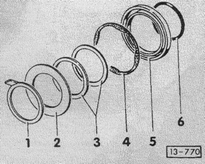
Lightly coat both sides of camshaft shim -1- with engine oil and install with the lip facing the crankshaft lifter.
Insert spacer -2- (∅ 81 mm) and screw on the flywheel. Parts -3- to -6- remain removed.
Axial play is checked in the same way as on models manufactured before November 85. Subtract 0.10 mm from the measurement result (mean end play).
Remove flywheel, adjust axial play by replacing both spacers -3-. The washers are etched with their thickness. If required, the washer thickness can be measured with a caliper.
Attention: Two distance washers -3- must be fitted.
Lubricate all parts -2- to -6- with engine oil and insert. Screw on the flywheel.
Check the end play again.
Visitor comments