English Русский
Български
Беларускі
Український
Српски
Hrvatski
Română
Polski
Slovenský
Magyar
  |  Articles  |  Sitemap  |  Contacts  |    |
Car maintenance Ford Car maintenance Hyundai Car maintenance Chevrolet Car maintenance BMW Car maintenance Audi Car maintenance Opel Car maintenance AvtoVAZ
VWmanual.ru


Main   Passat   Golf   Polo   Touareg   Tiguan   Sharan   Transporter   Others  
Transporter T3 (1979-1992) Transporter T4 (1990-2003)

Removal and installation connecting rods (VW Transporter T3)

  • Main
  • Transporter
  • Transporter T3
  • Petrol engines
  • Engine repair
  • Removal and installation connecting rods
            0


Contents: Removal ↓ Examination ↓ Installation ↓

Removal


Remove the crankshaft.

Remove the crankshaft.


Mark the corresponding connecting rods and bearing shells

Loosen the connecting rod nuts and remove the connecting rod caps, connecting rod rods and bearing shells. Mark the bearing shells. It is recommended to stack all removed parts in the order of installation.

Examination


Inspect the connecting rods for external damage.

The connecting rod cap fastening bolts must not be broken or crushed. If the bolts are damaged, replace the entire connecting rod.

The connecting rods must be replaced as a set.
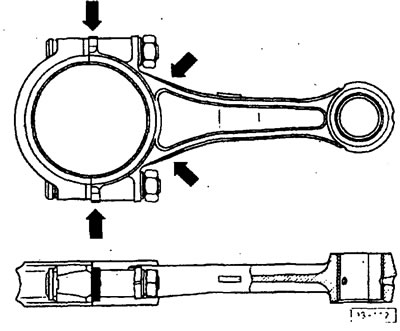
The connecting rods must be replaced as a set.


When replacing connecting rods, their weight must be checked, since the difference in weight of individual connecting rods must not exceed? g. Weigh the connecting rods without bearing shells.


If necessary, modify the connecting rods in the places indicated in the figure. This can reduce the weight by 8 g.

Check the connecting rod head bushing. With a new bushing, the unheated piston rod should enter with light finger pressure.

If necessary, balance the connecting rods (work at a service station).

Installation


Wash all parts in gasoline and lubricate with engine oil.

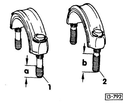
Depending on the design, if necessary, replace 6 connecting rod caps. 2 types of bolts are installed:

1 - rigid bolt, length of threaded part a - about 13 mm, does not change.

1 - rigid bolt, length of threaded part a - about 13 mm, does not change.
2 — Expanding bolt, threaded length b = about 30 mm, must be replaced, as the expanding bolt is released with each tightening. Observe different tightening methods.
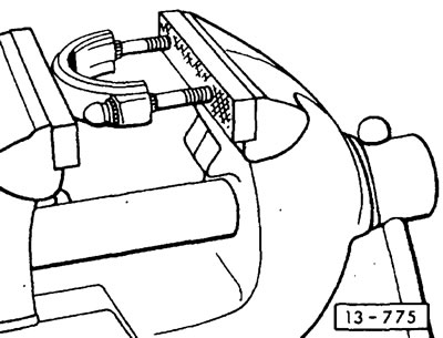

2 — Expanding bolt, threaded length b = about 30 mm, must be replaced, as the expanding bolt is…


To remove the connecting rod cap bolts, it is advisable to clamp the cap in a vice, as shown in the figure. Use a suitable press to press new bolts into the connecting rod caps.


Insert bearing shells and connecting rods in accordance with the markings made. The parts must be installed in their original places.
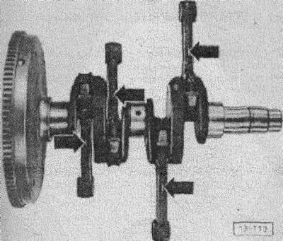
Insert bearing shells and connecting rods in accordance with the markings made. The parts must be…


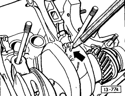
When installing, the mark on the connecting rod should be located above the "arrow".

Unscrew the new nuts. First remove the protective grease from the nuts and lubricate them with engine oil.

Tighten the nuts on the three rigid connecting rod cap bolts to a tightening torque of 45 Nm.

For stretch bolts (see "2" in Figure 13-792), the nuts are tightened in 2 passes. This requires a torque wrench.

1st pass: tighten the nuts with a torque wrench to 30 Nm.

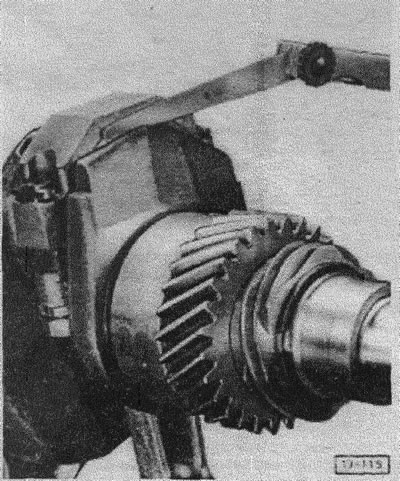
2nd pass: tighten the nuts with a hard wrench by 180° (1/2 turn). For better reading of the angle of rotation, first apply marks on the engine with chalk. There are also special protractors for turning fasteners at certain angles, for example, from Hazet.

After assembly, the connecting rods should tip downwards under their own weight.

After assembly, the connecting rods should tip downwards under their own weight.


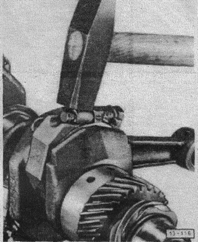
Minor distortions that occur when tightening the bolts between the bearing halves can be eliminated by lightly striking both sides of the connecting rod with a hammer.

Minor distortions that occur when tightening the bolts between the bearing halves can be eliminated…


Check the connecting rod axial clearance with a feeler gauge. The wear limit is max. 0.7 mm.

This article is available at russian, bulgarian, belarusian, ukrainian, serbian, croatian, romanian, polish, slovak, hungarian
The text has been checked: Tarasov Ivan

Share information:

Previous articles
Removal and installation the crankshaft
Removal and installation the camshaft
Disassembly and assembly of the engine crankcase
Checking and adjusting the axial play of the crankshaft
Removal and installation the flywheel, replacing the crankshaft seal
Checking cylinder bores
Next articles
Removal and installation the crankshaft oil seal
Removal and installation the belt pulley
Engine fault diagnostics
Removal and installation the engine beam


Similar articles from other manuals for VW cars:
Disassembly and assembly of pistons and connecting rods Passat B6 (2005-2010)
Removal pistons and connecting rods Golf 2 (1984-1993, petrol)
Connecting rod and piston group Polo 3 (1995-2003)
Disabling and connecting airbags Touareg 1 (2002-2006)
Parts and assemblies of transverse levers and transverse rods Tiguan 1 (2007-2015)
Removal pistons and connecting rods Sharan 1 (1995-2000)
Disassembly and assembly of pistons and connecting rods Caddy 3 (2003-2010)
Link to this page in different formats


Visitor comments


No comments yet


How much will 37 + 34 =


Transporter T4 
  • General information
  • User manual
  • Maintenance
  • Power unit
  • Engine repair
  • Ignition system
  • Lubrication system
  • Cooling system
  • Fuel system (petrol)
  • Fuel system (diesel)
  • Injection system (petrol)
  • Exhaust system
  • Transmission
  • Clutch
  • Car gearbox
  • Chassis
  • Car suspension
  • Steering
  • Brake system
  • Wheels and tires
  • Body
  • Exterior
  • Interior
  • Doors and windows
  • Heating system
  • Electrical equipment
  • Equipment and devices
  • Lighting and signaling
  • Power devices
  • Electrical circuits
Transporter T3 
  • General information
  • Maintenance
  • Petrol engines
  • Engine repair
  • Lubrication system
  • Cooling system
  • Power and exhaust system
  • Carburetor 34 PICT
  • Carburetors 2E3 and 2E4
  • Fuel injection system
  • Ignition system
  • Diesel engines
  • Engine repair
  • Lubrication system
  • Cooling system
  • Power and exhaust system
  • Transmission
  • Clutch
  • Car gearbox
  • Chassis
  • Front suspension
  • Rear suspension
  • Steering
  • Brake system
  • Body
  • Body and interior elements
  • Doors, locks and windows
  • Electrical equipment
  • Lighting system
  • Equipment and devices
  • Power devices (diesel)
  • Power devices (petrol)
  • Wiring diagrams (diesel)
  • Wiring diagrams (petrol)
VWmanual.ru © 2016-2026 | Mobile version | News and articles | Sitemap: EN BG BY UA RS HR RO PL SK HU | Write message | Site search
Passat B2 • Passat B3 • Passat B4 • Passat B5 • Passat B6 • Golf 1, diesel • Golf 1, petrol • Golf 2, petrol • Golf 2 • Golf 3 • Golf 4 • Golf 5 • Polo 3 • Polo 4 • Touareg 1 • Tiguan 1 • Sharan 1 • Transporter T3 • Transporter T4 • LT 28 • LT 2D • Beetle • Caddy 3 •
Our website uses cookies to ensure functionality and convenience.