



Contents: Checking the pistons ↓ Checking the thermal clearance of…↓ Checking the piston ring clearance…↓ Checking the cylinder diameter ↓ Piston and cylinder dimensions ↓
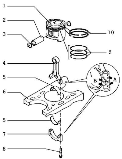
Fig. 2.27. Connecting rod and piston group: 1 – piston; 2 – piston pin; 3 – retaining ring; 4 – connecting rod; 5 – bearing shell; 6 – cylinder block; 7 – connecting rod cover; 8 – connecting rod cover mounting bolt; 9 – oil scraper rings; 10 – compression rings
Note: All support and working surfaces must be lubricated with engine oil before installation.
Checking the pistons
Measure approximately 12 mm from the bottom edge, at right angles to the piston pin axis. The maximum permissible deviation from the nominal size is 0.04 mm.
Checking the thermal clearance of piston rings
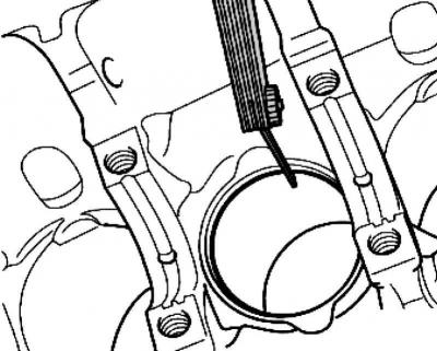
Fig. 2.28. Checking the thermal clearance of piston rings
Drive the ring from above at a right angle to the lower hole of the cylinder, at a distance of about 15 mm from its edge (Fig. 2.28).
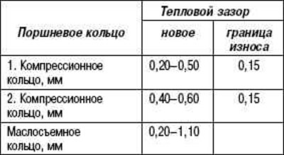
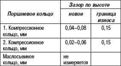
Checking the piston ring clearance by height
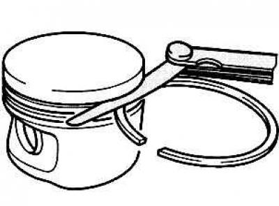
Fig. 2.29. Checking the piston ring clearance by height
Before checking, clean the ring groove (Fig. 2.29).
Checking the cylinder diameter
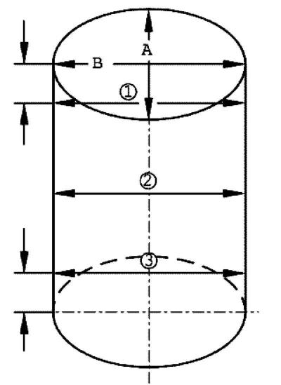
Fig. 2.30. Cylinder diameter check diagram
Take measurements crosswise in three places in transverse direction B and longitudinal direction B (Fig. 2.30). The maximum permissible deviation from the nominal size is 0.08 mm.
Note: Do not measure cylinder diameters when the cylinder block is secured to the engine and transmission clamp, as this may result in incorrect results.
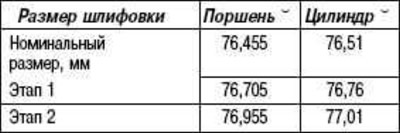
Piston and cylinder dimensions
Visitor comments